
Device and method for driving motor rotor hot jacket

A technology for driving motors and thermal sleeves, which is applied in the direction of electromechanical devices, manufacturing motor generators, adjusting/balancing rotors, etc. It can solve the problems of long contact surface and inability to directly complete assembly, etc., and achieve good heat preservation effect

Inactive Publication Date: 2021-05-07
CHINA INSTITUTE OF ATOMIC ENERGY
View PDF9 Cites 1 Cited by
  • Summary
  • Abstract
  • Description
  • Claims
  • Application Information

AI Technical Summary

Problems solved by technology

The length of the cylindrical rotor core is about 240mm, and the length of the rotor shaft is about 400mm. The rotor shaft needs to pass through the inner hole at the center of the rotor core. The contact surface between the two is long, and the assembly cannot be completed directly at room temperature.

Method used


Image

  • Device and method for driving motor rotor hot jacket

Examples


Embodiment Construction

[0022] The present invention will be further described below in conjunction with the accompanying drawings and embodiments.

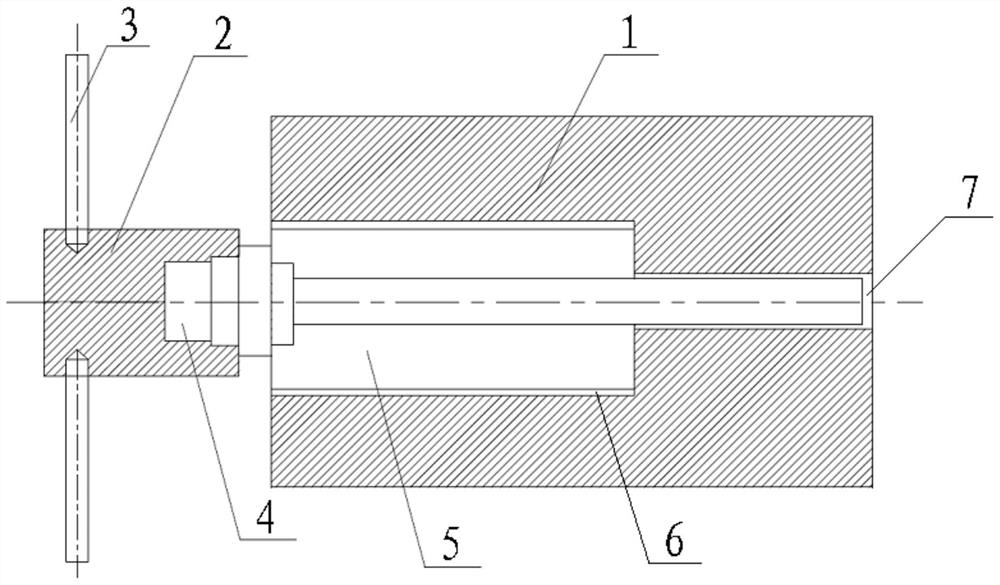
[0023] Such as figure 1 As shown, the present invention provides a device for driving a motor rotor shrink fit, which is used to fit a straight rotor core 5 on the rotor shaft 4, including a shrink fit tire core capable of accommodating the rotor core 5 1. It also includes a rotating sleeve 2 that can be arranged at one end of the rotor shaft 4 .

[0024] The heat-fit tire core 1 is provided with a chamber 6 capable of accommodating the rotor core 5. The top of the chamber 6 is provided with an opening and the bottom is provided with a plane. The opening of the chamber 6 is located on the top of the heat-fit tire core 1. The rotor core 5 can be placed vertically into the chamber 6 through the opening.

[0025] The chamber 6 is cylindrical, and a through hole 7 is provided at the center of the plane of the bottom of the chamber 6 , and the through hole...


PUM


Abstract

The invention belongs to the technical field of motor rotor shaft machining, and particularly relates to a device and a method for driving a motor rotor hot jacket. The device is used for sleeving a straight cylinder type rotor iron core (5) on a rotor shaft (4), and the device comprises a hot jacket tire core (1) capable of accommodating the rotor iron core (5), and further comprises a rotating sleeve (2) capable of being arranged at one end of the rotor shaft (4). According to the invention, the rotor iron core (5) and the rotor shaft (4) can be assembled in place, and a hot jacket tire core (1) can play a good heat preservation role, so that the situation that the rotor shaft (4) cannot be assembled to the bottom due to too fast cooling of the rotor iron core (5) after the rotor iron core (5) is discharged from a furnace, and hot jacket failure is caused is prevented; and the rotor iron core (5) and the rotor shaft (4) can be tightly connected, the magnitude of interference is (+ 0.02-+ 0.03) mm, and the requirement of the magnitude of interference can be met.

Description

technical field [0001] The invention belongs to the technical field of motor rotor shaft processing, and in particular relates to a device and method for driving a motor rotor shrink sleeve. Background technique [0002] The control rod drive mechanism (CRDM) is one of the key equipment of the reactor, which plays the role of starting and stopping the reactor, adjusting and compensating the power of the reactor. Among them, the control rod drive mechanism mainly plays the role of adjusting the reactivity, and needs to frequently drive the control rod assembly to move up and down. The demonstration fast reactor CRDM is a motor-driven type, and a special motor is used as a power source to drive the main shaft transmission chain to realize the up and down movement of the control rod assembly. The CRDM drive motor is a compound motor. The motor rotor is composed of a claw pole rotor and a reluctance rotor. In order to prevent short circuit of the claw pole rotor, the rotor shaft...

Claims


Application Information

Patent Timeline
IPC IPC(8): H02K15/02H02K15/12H02K15/16B25B27/14
CPCB25B27/14H02K15/02H02K15/028H02K15/12H02K15/16H02K2213/03
Inventor 夏凡靳峰雷郑富磊王明政陈树明杨孔雳吴宣东来海丰靳定坤安海峰
Owner CHINA INSTITUTE OF ATOMIC ENERGY
Features
  • Generate Ideas
  • Intellectual Property
  • Life Sciences
  • Materials
  • Tech Scout
  • Unparalleled Data Quality
  • Higher Quality Content
  • 60% Fewer Hallucinations
Learn More