Solar cell panel with self-cleaning mechanism

A solar panel and self-cleaning technology, applied in electrical components, photovoltaic power generation, photovoltaic modules, etc., can solve problems such as difficult solar panel cleaning, achieve utilization, ensure reliability, and improve utilization

Active Publication Date: 2021-05-07
宁波光年太阳能科技开发有限公司
4 Cites 1 Cited by

AI-Extracted Technical Summary

Problems solved by technology

The former has potential safety hazards during the cleaning process,...

Method used

Solar panel 1 mounting mechanism side is provided with support 7, is installed with the impeller 6 that follows wind rotation on support 7 simultaneously and realizes that wind energy is converted into mechanical energy, and the rotating disk that drives support 7 while rotating impeller 6 is installed 5 rotates to realize the transmission of power without installing a power device. The push rod connected to the turntable 5 pushes the sliding block 4 installed on the guiding mechanism 2 to move back and forth along the guiding mechanism 2, effectively improving the utilization of wind energy; at the same time, the two sliding blocks Between 4, a cleaning brush 3 is rotated and installed, and the installed cleaning brush 3 rolls along the surface of the solar panel 1 under the drive of the sliding block, so as to facilitate th...

Abstract

The invention discloses a solar cell panel with a self-cleaning mechanism, and relates to the technical field. The solar cell panel with the self-cleaning mechanism comprises a solar cell panel, a bottom frame and a mounting seat arranged on the bottom frame, wherein guide mechanisms are mounted on two opposite side surfaces of the solar cell panel; a cleaning brush is rotatably mounted between two sliding blocks, and the mounted cleaning brush moves along the surface of the solar cell panel; a support is vertically installed on one side of the bottom frame, an impeller rotating along with wind is installed at the top end of the support, meanwhile, a rotating disc meshed with a gear arranged at the bottom of the impeller is further installed on the support, a push rod is rotatably installed on the rotating disc, and the other end of the push rod is movably connected with the sliding block located on the upper side. The rotating impeller drives the rotating disc rotationally installed on the support to rotate at the same time, power transmission is achieved, no power device needs to be installed, the push rod connected to the rotating disc pushes the sliding blocks installed on the guide mechanisms to move back and forth along the guide mechanisms, and the utilization of wind energy is effectively improved.

Application Domain

PhotovoltaicsPhotovoltaic energy generation

Technology Topic

PhysicsEngineering +7

Image

  • Solar cell panel with self-cleaning mechanism
  • Solar cell panel with self-cleaning mechanism
  • Solar cell panel with self-cleaning mechanism

Examples

  • Experimental program(1)

Example Embodiment

[0026] The technical solutions in the embodiments of the present invention will be clearly and completely described below with reference to the accompanying drawings in the embodiments of the present invention. Obviously, the described embodiments are only a part of the embodiments of the present invention, but not all of the embodiments. Based on the embodiments of the present invention, all other embodiments obtained by those of ordinary skill in the art without creative efforts shall fall within the protection scope of the present invention.
[0027] In the description of the present invention, it is to be understood that the terms "opening", "upper", "lower", "thickness", "top", "middle", "length", "inside", "around", etc. Indicates the orientation or positional relationship, only for the convenience of describing the present invention and simplifying the description, rather than indicating or implying that the components or elements referred to must have a specific orientation, are constructed and operated in a specific orientation, and therefore should not be construed as a limitation of the present invention .
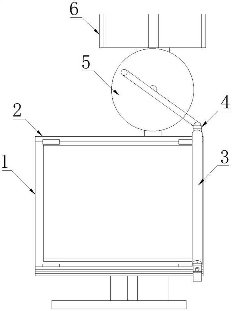
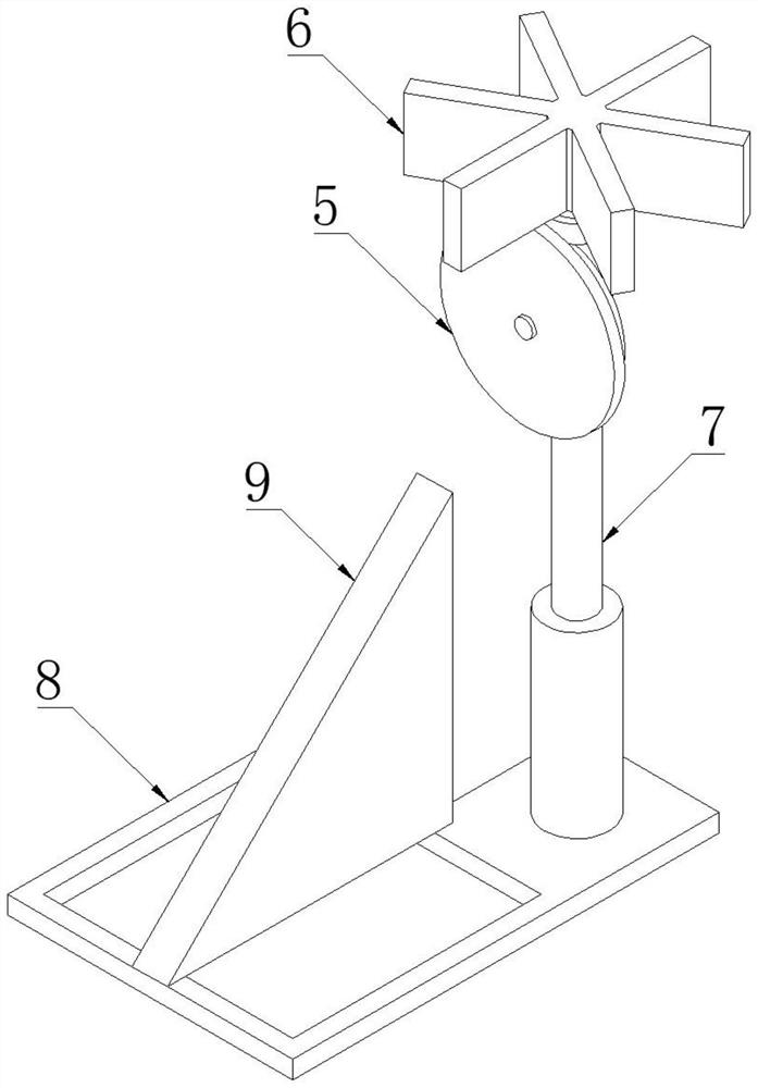
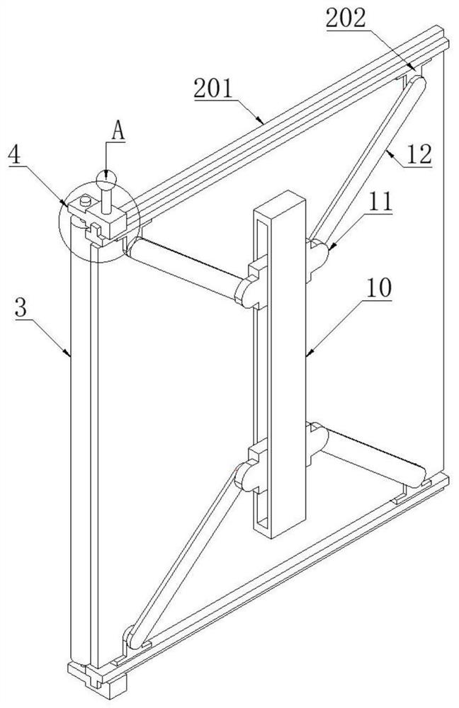
[0028] see Figure 1-5 As shown, the present invention is a solar cell panel with a self-cleaning mechanism, comprising a solar cell panel 1, a base frame 8 and a mounting seat 9 provided on the base frame 8, and guides are installed on opposite sides of the solar cell panel 1 Mechanism 2, a fixing mechanism 10 is installed on the back of the solar panel 1, and two limit blocks 11 with adjustable spacing are installed in the fixing mechanism 10, and the limit blocks 11 are connected with the guide mechanism 2 through the connecting rod 12;
[0029] Wherein, the solar cell panel 1 is fixedly installed on the mounting seat 9 through the provided fixing mechanism 10;
[0030] A sliding block 4 is slidably installed on each guiding mechanism 2, and a cleaning brush 3 is rotatably installed between the two sliding blocks 4, and the installed cleaning brush 3 moves along the surface of the solar cell panel 1;
[0031] A bracket 7 is installed vertically on one side of the bottom frame 8, and the top of the bracket 7 is installed with an impeller 6 that rotates with the wind. A push rod is rotatably installed, and the other end of the push rod is movably connected with the sliding block 4 on the upper side.
[0032] The mounting surface of the mounting seat 9 is an inclined surface, and the inclination angle of the inclined surface is in the range of 30°-60°; the guide mechanism 2 includes a guide rail 201 and a card seat 202, the guide rail 201 and the installed side are parallel to each other, and the bottom surface of the guide rail 201 is stacked. There are two clamps 202 that are clamped to the side of the solar cell panel 1 , and the clamps 202 are provided with pins connected to the connecting rod 12 .
[0033] A number of bristles are annularly distributed on the peripheral side of the cleaning brush 3 , which is convenient for cleaning the floating dust on the surface of the solar cell panel 1 .
[0034] The sliding block 4 includes a snap portion 401 and an extension block 403. The snap portion 401 is provided with a snap slot 402, and the snap slot 402 is snapped on a protrusion provided on the guide rail 201; an extension block extends from one side of the snap portion 401. 403, a through hole 404 is opened on the extension block 403, and the shaft body provided at the end of the cleaning brush 3 is rotated and installed in the through hole 404; A sphere 406 is provided. The turntable 5 is provided with an eccentric pin, which is connected with the sphere 406 of the clamping portion 401 through a push rod; the rotating turntable 5 drives the clamping portion 401 to reciprocate along the guide rail 201 .
[0035] The opposite ends of the limit block 11 are provided with hinge seats, and each hinge seat is hinged with a connecting rod 12; the fixing mechanism 10 is a hollow structure, and the end of the fixing mechanism 10 is installed with an adjusting bolt 13, and the end of the adjusting bolt 13 is connected with the end of the adjusting bolt 13. The limit block 11 is in contact, the fixing mechanism 10 installed on the back of the solar panel 1, and the limit block 11 is movably installed in the fixing mechanism 10, and the time interval between the two limit blocks is changed by the installed adjusting bolt 13, which is convenient for the connecting rod to be installed. 12 is in a tensioned state to ensure the reliability of the fixation of the guide mechanism 2 clamped to the side of the solar panel 1 .
[0036]A bracket 7 is provided on one side of the installation mechanism of the solar panel 1, and an impeller 6 that rotates with the wind is installed on the bracket 7 to convert wind energy into mechanical energy. The rotating impeller 6 drives the turntable 5 installed on the bracket 7 to rotate, The power transmission is realized without installing a power device. The push rod connected to the turntable 5 pushes the sliding block 4 installed on the guiding mechanism 2 to reciprocate along the guiding mechanism 2, which effectively improves the utilization of wind energy; at the same time, between the two sliding blocks 4 A cleaning brush 3 is rotatably installed, and the installed cleaning brush 3 rolls along the surface of the solar panel 1 under the driving of the sliding block, so as to clean the floating dust on the surface of the solar panel 1 and realize the utilization of wind energy.
[0037] In the description of this specification, description with reference to the terms "one embodiment," "example," "specific example," etc. means that a particular feature, structure, material, or characteristic described in connection with the embodiment or example is included in at least one aspect of the present invention. in one embodiment or example. In this specification, schematic representations of the above terms do not necessarily refer to the same embodiment or example. Furthermore, the particular features, structures, materials or characteristics described may be combined in any suitable manner in any one or more embodiments or examples.
[0038] The above-disclosed preferred embodiments of the present invention are provided only to help illustrate the present invention. The preferred embodiments do not exhaust all the details, nor do they limit the invention to only the described embodiments. Obviously, many modifications and variations are possible in light of the contents of this specification. These embodiments are selected and described in this specification in order to better explain the principles and practical applications of the present invention, so that those skilled in the art can well understand and utilize the present invention. The present invention is to be limited only by the claims and their full scope and equivalents.

PUM

no PUM

Description & Claims & Application Information

We can also present the details of the Description, Claims and Application information to help users get a comprehensive understanding of the technical details of the patent, such as background art, summary of invention, brief description of drawings, description of embodiments, and other original content. On the other hand, users can also determine the specific scope of protection of the technology through the list of claims; as well as understand the changes in the life cycle of the technology with the presentation of the patent timeline. Login to view more.

Similar technology patents

Method for extracting peanut polypeptide from peanut meal

PendingCN108300751AImprove utilizationImprove finished product quality
Owner:广西南宁人人想食品有限公司

Rotating disc type automatic assembly line

Owner:武汉孚特锂能科技有限公司

Wall type folding chair for cylindrical wall manned vessel

PendingCN107117182AImprove utilizationReasonable use of space
Owner:烟台福皓医疗设备有限公司

Remote medical system

PendingCN111489835AImplement interaction managementImprove utilization
Owner:四川君德利远程医疗科技有限公司

Classification and recommendation of technical efficacy words

  • Improve utilization
  • Realize utilization

Integrated navigation method based on fault-tolerant Kalman filtering

ActiveCN109373999AImprove utilizationImprove robust performance
Owner:HARBIN ENG UNIV

Refrigeration method utilizing natural cold source, energy-saving system and storage medium

PendingCN114025575ARealize utilizationextended availability
Owner:CHINA UNITED NETWORK COMM GRP CO LTD

Environmentally-friendly green life multifunctional cabin and utilization method of water resource and multi-energy

InactiveCN109138517ARealize utilizationRealize multi-energy utilization
Owner:重庆市南岸区南坪四海小学校

Micro-power energy taking device, system and method based on direct-current corona ion current

InactiveCN112436498ARealize utilizationachieve self-supply
Owner:NORTH CHINA ELECTRIC POWER UNIV (BAODING)
Why Eureka
Try Eureka