Supercharge Your Innovation With Domain-Expert AI Agents!

Steam cooling separator structure

A technology of a gas-cooled separator and separator, which is applied in the direction of combustion type, combustion method, lighting and heating equipment, etc., can solve the problem of easy coking of the gas-cooled separator, and achieve the effect of ensuring stability

Pending Publication Date: 2021-05-11
WUXI HUAGUANG BOILER
View PDF0 Cites 0 Cited by
  • Summary
  • Abstract
  • Description
  • Claims
  • Application Information

AI Technical Summary

Problems solved by technology

[0004] In order to solve the problem that the existing gas-cooled separator is easy to coke, the present invention provides a structure of the gas-cooled separator, which can effectively solve the problem of coking

Method used


Image

  • Steam cooling separator structure
  • Steam cooling separator structure
  • Steam cooling separator structure

Examples


Embodiment Construction

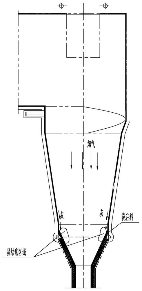
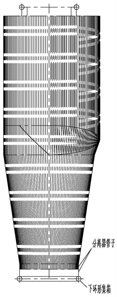
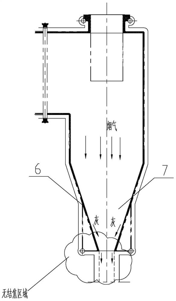
[0015] See image 3 , Figure 4 , Figure 5 , Image 6 As shown, a gas-cooled separator structure, which includes an upper annular header 1 and a lower annular header 2, the upper annular header 1 and the lower annular header 2 are connected by a separator pipe 3 arranged in a ring, The upper parts of adjacent separator pipes 3 are connected by flat steel. The separator pipes 3 include a first separator pipe 4 and a second separator pipe 5 arranged at intervals. The first separator pipe 4 includes a first upper vertical Section 4-1 and lower inclined section 4-2, the second separator pipe 5 includes a second upper vertical section 5-1, a middle inclined section 5-2, a lower vertical section 5-3, a first upper vertical section 4-1 The height corresponds to the second upper vertical section 5-1 and forms a cylindrical shape. The first upper vertical section 4-1 and the second upper vertical section 5-1 are connected to the upper annular header 2 through the upper elbow 8, and...


PUM


Abstract

The invention relates to the technical field of circulating fluidized bed biomass boilers, in particular to a steam cooling separator structure which can effectively solve the problem of coking and comprises an upper ring header and a lower ring header, and the upper ring header and the lower ring header are connected through separator pipes arranged in an annular mode. The steam cooling separator structure is characterized in that the lower ends of part of the separator pipes are connected with the inner side of the lower ring header, and the lower ends of the rest separator pipes are connected with the upper end of the lower ring header.

Description

technical field [0001] The invention relates to the technical field of circulating fluidized bed biomass boilers, in particular to a steam-cooled separator structure. Background technique [0002] As the country's requirements for pollutant emissions become increasingly stringent, the demand for clean energy technology for power plant boilers and industrial boilers is also gradually increasing. It has received more and more attention and has developed rapidly in recent years. [0003] The separator is an important component of the circulating fluidized bed boiler, and the form and arrangement of the separator have a great influence on the performance of the boiler. The traditional steam-cooled separator is generally equipped with an upper annular header and a lower annular header. There are annular uniformly distributed pipes between the upper and lower annular headers. The upper part of the pipe is a vertical section, and the middle part is inclined inward, forming a funne...

Claims


Application Information

Patent Timeline
IPC IPC(8): F23C10/08F23C10/18
CPCF23C10/08F23C10/18
Inventor 黄磊孙晶晶杨巍冯爽
Owner WUXI HUAGUANG BOILER
Features
  • R&D
  • Intellectual Property
  • Life Sciences
  • Materials
  • Tech Scout
  • Unparalleled Data Quality
  • Higher Quality Content
  • 60% Fewer Hallucinations
Learn More