A stamping device for processing crane trolley parts
A technology of parts processing and stamping device, which is applied in the direction of feeding device, positioning device, storage device, etc. It can solve the problems of easy error in the placement of the stopper mounting frame, cumbersome processing procedures of the stopper mounting frame, etc., and achieve the effect of convenient processing
- Summary
- Abstract
- Description
- Claims
- Application Information
AI Technical Summary
Problems solved by technology
Method used
Image

Examples
Embodiment 1
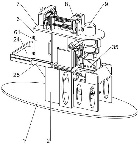
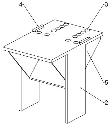
[0035] A stamping device for processing crane trolley parts, such as figure 1 and figure 2 As shown, it includes a base plate 1, a support platform 2, a baffle plate 4, an inclined frame 5, a holding frame 6, a cover plate 61, a mounting plate 7, a mobile punching mechanism 8 and a forming mechanism 9, and the top left side of the base plate 1 is installed There is a supporting platform 2, and at least five feeding holes 3 are opened on the front and rear sides of the top of the supporting platform 2. Plate 4, the blanking holes 3 on the front and rear sides are located between the front and rear baffle plates 4, an inclined frame 5 is installed on the underside of the inner side wall of the support platform 2, and a holding frame 6 is installed on the left side of the top of the support platform 2. Put the rear side wall left part of frame 6 to be equipped with cover plate 61 by hinge, the top of containing frame 6 is connected with mounting plate 7, and the top of mounting...
Embodiment 2
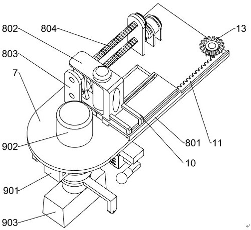
[0038] On the basis of Example 1, such as Figure 3-9 As shown, the mobile punching mechanism 8 includes a first sliding frame 801, a moving frame 802, a first support plate 803, a screw 804, a threaded sleeve 805, a first fixed plate 806, a first pulley 807, and a first belt 808. , support plate 809, deceleration motor 810, electric push rod 811, slide rail 812, slide block 813, installation frame 814, electric drill 815, tension spring 817, L-shaped plate 818, slide block 819 and guide parts, the first slide frame 801 Fixedly connected to the right front part of the top of the mounting plate 7, the top rear side of the first sliding frame 801 is slidingly provided with a mobile frame 802, and the left and right sides of the top rear side of the mounting plate 7 are equipped with a first support plate 803. A lead screw 804 is rotatably installed between the upper and lower sides of the two first support plates 803, the lead screw 804 is provided with a threaded sleeve 805, an...
Embodiment 3
[0043] On the basis of Example 2, such as image 3 , Figure 10 and Figure 11 As shown, the forming mechanism 9 includes a first mounting frame 901, a hydraulic cylinder 902, a stamping block 903, a second supporting plate 904, a blanking frame 905, a slanting plate 906, a forming frame 907, a pushing block 908, and a second limiter. Plate 909, slide bar 910, second fixed plate 911 and second back-moving spring 912, the first mounting frame 901 is affixed to the bottom of mounting plate 7, and the first mounting frame 901 is positioned at the right side of electric push rod 811, and mounting plate 7 A hydraulic cylinder 902 is embedded between the first installation frame 901, the lower end of the telescopic rod of the hydraulic cylinder 902 is fixedly connected with a stamping block 903, and the top of the bottom plate 1 on the right side of the first support plate 803 is installed with a second support plate 904, two front and rear A blanking rack 905 is fixedly connected...
PUM
 Abstract
Description
Claims
Application Information
 - R&D
- Intellectual Property
- Life Sciences
- Materials
- Tech Scout
- Unparalleled Data Quality
- Higher Quality Content
- 60% Fewer Hallucinations
Browse by: Latest US Patents, China's latest patents, Technical Efficacy Thesaurus, Application Domain, Technology Topic, Popular Technical Reports.
© 2025 PatSnap. All rights reserved.Legal|Privacy policy|Modern Slavery Act Transparency Statement|Sitemap|About US| Contact US: help@patsnap.com