Separating type engine shell with efficient heat dissipation function

A separate technology for the engine shell, which is applied in the direction of engine components, engine frame, engine cooling, etc., can solve the problems of shortening the service life of the engine, reducing the power of the engine, and reducing the service life of the engine, so as to improve the heat dissipation efficiency, The effect of avoiding shortened service life and reducing the chance of damage

Active Publication Date: 2021-05-18
重庆峰聂机械有限公司
View PDF14 Cites 2 Cited by
  • Summary
  • Abstract
  • Description
  • Claims
  • Application Information

AI Technical Summary

Problems solved by technology

[0002] The engine will generate a large amount of heat during operation. If the engine cannot be cooled, the power of the engine may be reduced, and the service life of the engine may even be shortened. Air cooling and water cooling can cool down

Method used


Image

  • Separating type engine shell with efficient heat dissipation function
  • Separating type engine shell with efficient heat dissipation function
  • Separating type engine shell with efficient heat dissipation function

Examples


Example Embodiment

[0025]Example 1:

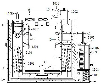
[0026]SeeFigure 1-7The present invention provides a technical solution: an engine housing having a separate high heat radiation function, comprising a housing 1, the housing 1 is provided with air cooling means 10, and a rapid cooling mechanism 11 dust mechanism 12, the housing 1 The top of the inner side is fixedly mounted having a U-shaped box 3, and two sets of filter layer plates 9 are mounted in the top of the housing 1, and the inner bottom of the casing 1 is rotated and mounted, and one end of the rotation shaft 5 extends to the U-box 3. the engine is mounted and fixed inside the fixing table 8, the side of the outer wall of the housing 1 is fixedly mounted crush boxes 4, 4 fixed to a side crush boxes attached to the filler tube, provided with a check valve on the feed tube, the housing 1 The inner top is fixedly mounted having a dust filter box 6, and the housing 1 thus is fixed to one side of the U-shaped box 3, and the housing 1 is attached to the housing 1...

Example Embodiment

[0028]Example 2:

[0029]SeeFigure 1-7On the basis of the first example, the air-cooling mechanism 10 includes a fan 1001, an output tube 1002, a shot rod 1003, a fan blade 1004, a connecting tube 1005, and a blower tube 1006, and the fan 1001 is fixed to the top, fan of the housing 1. The output terminal of 1001 is fixedly mounted, and one end of the output tube 1002 passes through the top of the housing 1 and extends to the inside of the fan leaf transmission case 7, and the side of the fan leaf transmission case 7 is rotated to mounting a turn rod 1003, transfer One end of the rod 1003 extends to one side of the housing 1, the outer wall of the rotary rod 1003 is fixedly mounted with two sets of fan blade 1004, and the bottom fixing of the fan blade transmission box 7 is fixedly mounted, the connecting tube 1005 and the fan leaf transmission case 7 The internal communication, one end of the connecting tube 1005 is fixedly mounted with a blower tube 1006, the interior of the connecti...


PUM


Abstract

The invention discloses a separating type engine shell with an efficient heat dissipation function, and relates to the technical field of engines. The separating type engine shell with the efficient heat dissipation function comprises a shell body, an air cooling mechanism, a rapid cooling mechanism and a dust falling mechanism are arranged on the shell body, a U-shaped box is fixedly installed at the top of the inner side of the shell body, and two sets of filtering layer plates are installed at the top of the shell body in an embedded manner. According to the separating type engine shell with the efficient heat dissipation function, hot air in the shell body can be rapidly circulated, so that the heat dissipation efficiency in the shell body can be improved, it is guaranteed that an engine can normally run, dust in the shell body can be filtered and cleaned through the arrangement of a fine dust filter plate and a particle filter plate, the situation that the engine is damaged by excessive dust in the shell body is avoided, it can be guaranteed that the engine is not disturbed during use after the dust in the shell body is cleaned, and therefore the working efficiency of the engine can be improved.

Description

technical field [0001] The invention relates to the technical field of engines, in particular to a detached engine case with efficient heat dissipation function. Background technique [0002] The engine will generate a large amount of heat during operation. If the engine cannot be cooled, the power of the engine may be reduced, and the service life of the engine may even be shortened. Air cooling and water cooling can cool down the running engine at the same time, but the dust generated inside the engine cannot be cleaned. When there is too much dust inside the engine, the engine may not work normally and the service life of the engine will be reduced. A series of problems . Contents of the invention [0003] The object of the present invention is to provide a detached engine case with efficient heat dissipation function, so as to solve the problems raised in the above-mentioned background technology. [0004] In order to achieve the above object, the present invention p...

Claims


Application Information

Patent Timeline
IPC IPC(8): F01P1/00F01P9/06F01P11/12F02B77/13F02B77/04F16M1/00
CPCF01P1/00F01P9/06F01P11/12F02B77/13F02B77/04F16M1/00F01P2001/005
Inventor 李奇松郑俊雄
Owner 重庆峰聂机械有限公司
Why Eureka
Try Eureka