Test bench for testing electric drive axle

A test bench, electric drive technology, applied in the field of test benches, can solve the problems of limited application scope, inconvenient adjustment of the height of the support table, and inconvenient operation of staff of different heights.

Active Publication Date: 2021-05-18
GEYUAN POWER
15 Cites 0 Cited by

AI-Extracted Technical Summary

Problems solved by technology

[0002]The electric drive axle, that is, the drive axle, is composed of the final reducer, differential, wheel drive and drive axle housing, etc. The power of the motor turns over 90 degrees to change the transmission direction of the force, and the speed is reduced by the final reducer. After increasing the torque, it is distributed to the left and right axle shafts and driving wheels through the differential. Before the electric drive axle is put into use,...

Abstract

The invention discloses a test bench for testing an electric drive axle. The test bench comprises a supporting table, the four corners of the lower part of the supporting table are connected with height adjusting screw rods, the outer sides of the height adjusting screw rods are in engaged connection with screw cylinders, the outer sides of the screw cylinders are connected with tooth cylinders, a height driving motor is installed at the position, located among the four height adjusting screw rods, below the supporting table, the output shaft end of the height driving motor is connected with a driving gear, and the driving gear is connected with four tooth cylinders in an engaged mode. Through the arrangement of the height adjusting screw rods, the screw cylinders, the movable driving motor, the height driving motor, the driving gear and a tooth cylinder base, under the mutual cooperation of the structures, the function that the height of the supporting table is convenient to adjust is achieved, and the device is suitable for operators of different heights to operate, high in automation degree and high in stability. The test bench is suitable for testing the electric drive axle.

Application Domain

Vehicle testing

Technology Topic

Electric driveElectric machinery +3

Image

  • Test bench for testing electric drive axle
  • Test bench for testing electric drive axle
  • Test bench for testing electric drive axle

Examples

  • Experimental program(1)

Example Embodiment

[0029] The following will clearly and completely describe the technical solutions in the embodiments of the present invention with reference to the accompanying drawings in the embodiments of the present invention. Obviously, the described embodiments are only some, not all, embodiments of the present invention. Based on the embodiments of the present invention, all other embodiments obtained by persons of ordinary skill in the art without making creative efforts belong to the protection scope of the present invention.
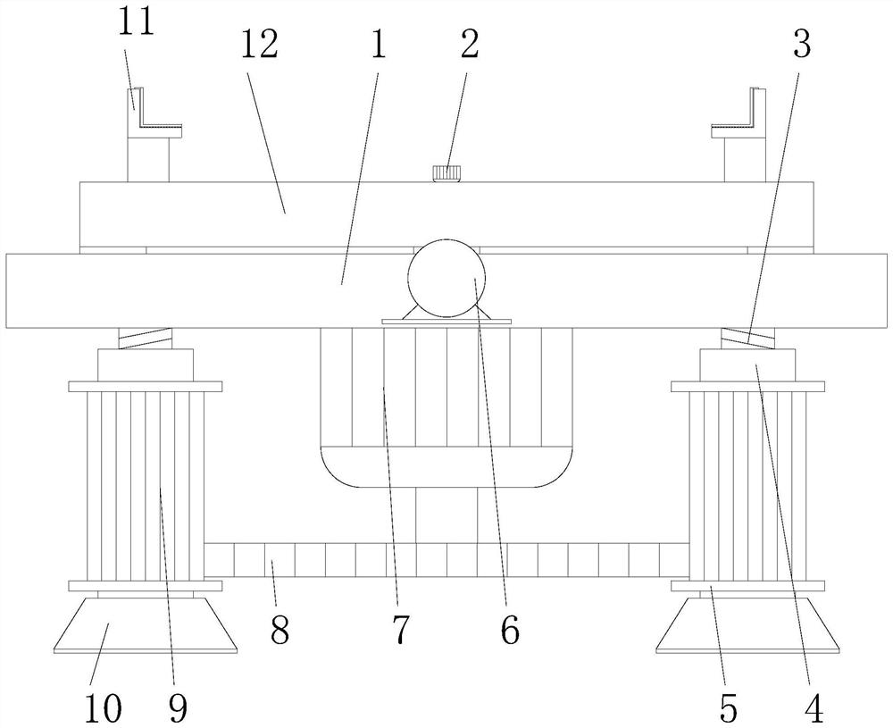
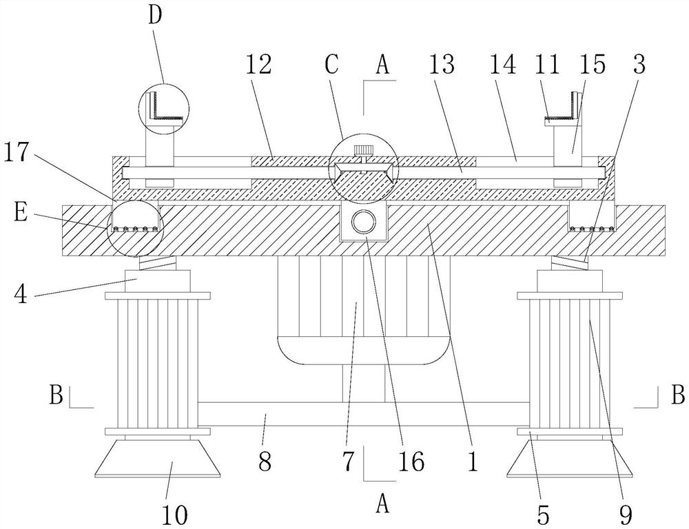
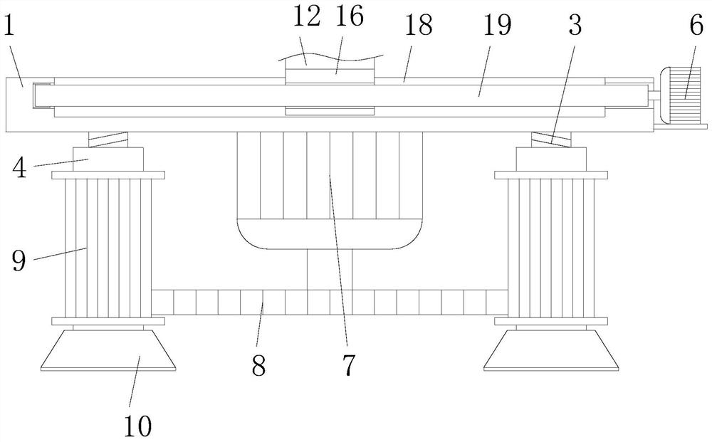
[0030] see Figure 1-9 , the present invention provides the following technical solutions: a test bench for electric drive axle testing, including a support platform 1, the four corners below the support platform 1 are connected with a height adjustment screw 3, and the outer sides of the height adjustment screw 3 are engaged and connected There is a screw barrel 4, the outer side of the screw barrel 4 is connected with a gear barrel 9, and a height drive motor 7 is installed under the support table 1 and between the four height adjustment screw rods 3, and the output shaft end of the height drive motor 7 is connected to There is a driving gear 8, the driving gear 8 is meshed with four gear cylinders 9, the bottom of the screw cylinder 4 is connected with a base 10, and the top of the support table 1 is connected with a mounting plate 12, and both sides of the mounting plate 12 are provided with limit slides. Slot 14, the internal rotation of limit chute 14 is connected with clamping adjustment screw rod 13, and the side of two clamping adjustment screw rods 13 close to each other is connected with driven bevel gear 21, between the two driven bevel gears 21 The driving bevel gear 20 is meshed and connected between the upper side, and the clamping drive motor 2 is installed above the driving bevel gear 20 and in the upper middle position of the mounting plate 12, and the output shaft end of the clamping drive motor 2 extends to the mounting plate The inside of 12 is connected with the driving bevel gear 20, and the outside of the clamping adjustment screw 13 is meshed with a support screw block 15, and the top of the support screw block 15 is connected with an L-shaped clamping plate 11.
[0031] Specifically, the lower end of the screw barrel 4 is rotatably connected to the inside of the base 10 through a first bearing, and the ends of the two clamping adjustment screws 13 away from each other are rotatably connected to the inside of the mounting plate 12 through a second bearing.
[0032] By adopting the above technical solution, the stable rotation and placement of the screw barrel 4 and the clamping adjustment screw 13 are ensured.
[0033] Specifically, the lower end of the driving bevel gear 20 and the sides away from each other of the two driven bevel gears 21 are connected with a supporting rotating column, and the supporting rotating column is rotatably connected to the inside of the mounting plate 12 through a third bearing.
[0034] By adopting the above technical solution, it is convenient to ensure the stable rotation and placement of the driving bevel gear 20 and the driven bevel gear 21 .
[0035] Specifically, an L-shaped protective gasket 22 is connected to the upper surface of the L-shaped clamping plate 11 .
[0036]By adopting the above-mentioned technical scheme, it is convenient to effectively protect the electric drive axle, avoid excessive clamping force, cause damage to it, and bring unnecessary economic losses.
[0037] Specifically, the sides of the two L-shaped protective gaskets 22 away from each other are connected with T-shaped guide blocks 24, and the inside of the L-shaped clamping plate 11 is provided with a T-shaped guide groove 23 at a position corresponding to the T-shaped guide block 24. , the bottom of the L-shaped protective gasket 22 is evenly connected with several elastic clips 29, and the inside of the L-shaped clamping plate 11 is provided with a slot 30 corresponding to the position of the elastic clips 29, and the elastic clips 29 are clipped on the clip. inside of the slot 30.
[0038] By adopting the above-mentioned technical scheme, it is convenient to realize the function of installing and dismounting the clamping drive motor 2, so that when the L-shaped protective gasket 22 ages after long-term use, it is easy to replace it, so as to ensure its electric drive in subsequent use. Bridges are better protected.
[0039] Specifically, a moving screw block 16 is connected to the lower middle position of the mounting plate 12, and a moving groove 18 is provided inside the support table 1 at a position corresponding to the moving screw block 16, and a moving adjusting screw rod 19 is connected to the inside of the moving groove 18 in rotation. , the moving screw block 16 is meshed and connected to the outside of the moving adjusting screw 19, one end of the moving adjusting screw 19 is rotatably connected to the inside of the support platform 1 through the fourth bearing, and the other end of the moving adjusting screw 19 extends through the supporting platform 1 to the supporting platform 1 The outside of the support table 1 is equipped with a mobile drive motor 6, and the output shaft end of the mobile drive motor 6 extends to the inside of the support table 1 and is connected with the movement adjustment screw 19.
[0040] By adopting the above-mentioned technical solution, it is convenient to move the mounting plate 12 , and further facilitate to realize the change of the position of the electric drive axle, so as to facilitate the testing of different positions of the electric drive axle.
[0041] Specifically, both sides below the mounting plate 12 are connected with support sliders 17, and a balance chute 25 is provided inside the support table 1 and at a position corresponding to the support slider 17, and the support slider 17 is slidably connected to the balance chute 25. internal.
[0042] By adopting the above technical solution, it is convenient to ensure the balance of the mounting plate 12 when it is moved and placed.
[0043] Specifically, several concave frames 27 are evenly connected to the inner bottom of the balance chute 25, and the outer side of the concave frame 27 is connected with anti-wear beads 28, which support the inside of the slider 17 and correspond to the positions of several anti-wear beads 28. Place limit track 26.
[0044] By adopting the above technical solution, it is convenient to reduce the abrasion between the support slider 17 and the inner wall of the balance chute 25 when moving.
[0045] Specifically, a silicone gasket is connected to the lower surface of the base 10 .
[0046] By adopting the above technical solution, it is convenient to ensure the stable placement of the device as a whole.
[0047] Specifically, the outer side of the screw barrel 4 and the upper and lower sides of the gear barrel 9 are connected with the limiting ring 5 .
[0048] By adopting the above technical scheme, it is convenient to limit the driving gear 8 and avoid the situation that the driving gear 8 is separated from the gear cylinder 9, so that the height adjustment screw 3 can be limited to avoid the situation that the height adjustment screw 3 is separated from the screw cylinder 4. , reducing unnecessary troubles.
[0049] The working principle and application process of the present invention: when using the present invention, firstly, the switch of the height drive motor 7 can be activated, and under the meshing action, the driving gear 8 can drive the four gear cylinders 9 to rotate, so that the screw cylinder 4 can rotate along the height The adjustment screw 3 rotates, and under the meshing action, the four height adjustment screws 3 drive the support platform 1 to move longitudinally. During this process, the base 10 plays an effective supporting role. Carry out longitudinal movement along the gear cylinder 9 (the limit ring 5 plays an effective limit effect), until the support table 1 is adjusted to a height suitable for the operator to operate, and the switch of the height drive motor 7 is turned off;
[0050] The operator then places the electric drive axle between the two L-shaped clamping plates 11, starts the switch of the clamping drive motor 2, and under the meshing action, the driving bevel gear 20 drives the driven bevel gear 21 to rotate, thereby Make the clamping adjustment screw 13 rotate inside the support screw 15, and under the meshing action, the two support screws 15 drive the L-shaped clamping plate 11 to move toward each other along the limit chute 14, and then the L-shaped protective gasket 22 Under the action of clamping the electric drive axle, it also plays an effective role in protecting the electric drive axle;
[0051] When performing the test operation, if it is necessary to test different positions of the electric drive axle, it is only necessary to start the switch of the mobile drive motor 6 to make the mobile adjustment screw 19 rotate inside the mobile screw block 16. The block 16 moves along the inside of the moving groove 18, and then the mounting plate 12 drives the electric drive bridge above it to move, and moves to the designated position, and then closes the switch of the mobile driving motor 6;
[0052] During the movement of the mounting plate 12, the supporting slider 17 moves along the inside of the balance chute 25, which effectively balances the mounting plate 12, and when the supporting slider 17 moves, the anti-wear beads 28 roll along the concave frame 27 At the same time, sliding along the inside of the limit rail 26 effectively reduces the wear between the support slider 17 and the inner wall of the balance chute 25;
[0053] After the device has been used for a period of time, if the L-shaped protective gasket 22 is aging, the lower end of the L-shaped protective gasket 22 can be pulled under the action of an external force, and under the elastic force of the elastic clip 29, the elastic clip 29 is disengaged. slot 30, and then pull up the T-shaped guide block 24, so that the T-shaped guide block 24 moves along the T-shaped guide slot 23 until the T-shaped guide block 24 is completely separated from the T-shaped guide slot 23, that is, the L-shaped protective gasket 22 is completely removed. Next, the new L-shaped protective gasket 22 is reinstalled.
[0054] Although the embodiments of the present invention have been shown and described, those skilled in the art can understand that various changes, modifications and substitutions can be made to these embodiments without departing from the principle and spirit of the present invention. and modifications, the scope of the invention is defined by the appended claims and their equivalents.

PUM

no PUM

Description & Claims & Application Information

We can also present the details of the Description, Claims and Application information to help users get a comprehensive understanding of the technical details of the patent, such as background art, summary of invention, brief description of drawings, description of embodiments, and other original content. On the other hand, users can also determine the specific scope of protection of the technology through the list of claims; as well as understand the changes in the life cycle of the technology with the presentation of the patent timeline. Login to view more.
Why Eureka
Try Eureka