Check patentability & draft patents in minutes with Patsnap Eureka AI!

Steel pipe column concrete pouring tool and method for house building municipal engineering

A steel pipe column and concrete technology, which is applied in construction, building structure, and construction material processing, can solve the problems of concrete sputtering, etc., and achieve the effects of weakening sputtering, increasing the range of discharge, and facilitating blanking

Active Publication Date: 2021-05-25
河南方元建筑工程有限公司
View PDF34 Cites 0 Cited by
  • Summary
  • Abstract
  • Description
  • Claims
  • Application Information

AI Technical Summary

Problems solved by technology

[0004] In view of the related technologies mentioned above, the inventor believes that there is a defect that concrete is easily splashed out from the steel pipe column

Method used


Image

  • Steel pipe column concrete pouring tool and method for house building municipal engineering
  • Steel pipe column concrete pouring tool and method for house building municipal engineering
  • Steel pipe column concrete pouring tool and method for house building municipal engineering

Examples


Embodiment 1

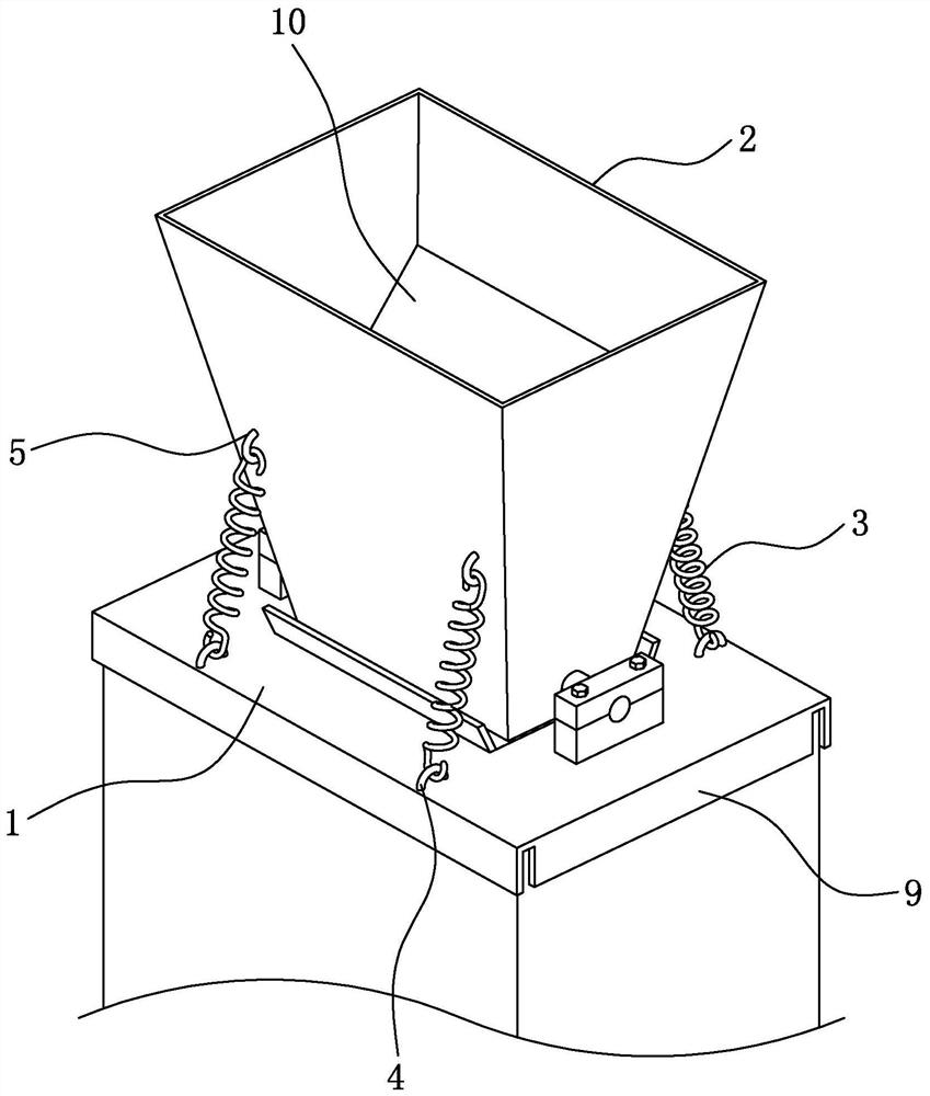
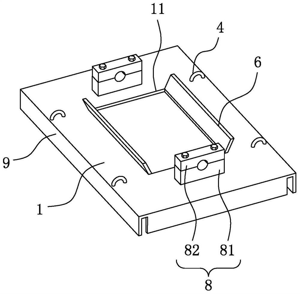
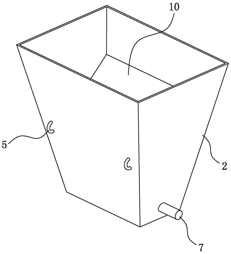
[0045]Referfigure 1 withfigure 2 The steel pipe pouring tool for the housing municipal engineering includes mounting plates 1 mounted at the top opening of the steel pipe column. The mounting plate 1 is positioned with the steel pipe column, and the surface of the mounting plate 1 is opened 11, the mounting plate 1 On the side, a tapered funnel 2 is mounted, the discharge port of the funnel 2 is disposed opposite the grouting port 11, and after being injected into the funnel 2, the concrete can pass through the discharge port of the funnel 2, into the grouting port 11 , Pouring concrete towards the steel tube column.

[0046]Referfigure 1 The edge of the mounting plate 1 is fixed at the same side positioning plate 9 in the mounting plate 1, and there is a certain gap between the positioning plates 9, facilitating the set of positioning plates 9 and the steel pillar. When the mounting plate 1 is mounted with the steel pipe post, the positioning plate 9 and the outer wall of the steel pi...

Embodiment 2

[0055]ReferFigure 4 , The steel pipe column concrete pouring method for housing construction municipal engineering includes the following steps.

[0056]S1: Select the mounting plate 1, which is possible to position the mount 1 set on the steel pipe post.

[0057]S2: On the support holder 81 of the mounting plate 1 by the rotation shaft 7, the compressor 82 is fixed to the support seat 81 by bolt, and the rotational relationship of the funnel 2 and the mounting plate 1 is realized, and the spring is hooked. On the second hanging ring 5 on the first hanging ring 4 on the mounting plate 1, a stable connection of the funnel 2 and the mounting plate 1 is realized.

[0058]S3: The mounting plate 1 with funnel 2 is hoisted to the top of the steel pipe, and the mounting plate is set on the top of the steel pipe.

[0059]S4: By placing the pump tube into the funnel 2, the pump tube is stabilized into the funnel 2, and the concrete flows from the funnel 2 into the steel pipe column to achieve pouring.

[0...


PUM


Abstract

The invention relates to a steel pipe column concrete pouring tool and method for house building municipal engineering, and relates to the technical field of building construction. The steel pipe column concrete pouring tool comprises a mounting plate mounted at an opening in the top of a steel pipe column, wherein the mounting plate is in positioning fit with the steel pipe column, a grouting opening is formed in the surface of a connector, a frustum-shaped funnel is mounted at the grouting opening, and a plurality of inclined guide plates are arranged in the funnel; the funnel is in a rectangular pyramid frustum shape; the funnel is rotationally connected with the mounting plate, elastic pieces are arranged on the two sides of the funnel in the rotating direction, and the two ends of each elastic piece are connected with the funnel and the mounting plate respectively; and the elastic pieces are springs, and the two ends of each spring are hooked on the funnel and the mounting plate. The steel pipe column concrete pouring tool and method have the advantage that the problem of concrete sputtering generated during steel pipe column pouring is solved.

Description

Technical field[0001]The present invention relates to the technical field of construction construction, in particular, involving a steel pipe column concrete pouring tool for housing municipal engineering.Background technique[0002]In the construction construction, it is often necessary to pour the concrete to the steel pipe. At present, the high-throwing method is currently used for steel column concrete. However, the pouring hole in the top of the steel column is generally small, and the diameter is still small than the pump tube diameter, when pouring It is difficult to achieve accurate docking of the pouring hole and the pump tube guide, which is easy to show that the concrete cannot be injected into the pouring hole in the predetermined goal, but the concrete sprayed in the surrounding problem, which not only caused resource waste and the cleanliness of the construction site, affecting construction efficiency .[0003]Steel tube (i.e., steel tube concrete column) refers to the for...

Claims


Application Information

Patent Timeline
Patent Type & Authority Applications(China)
IPC IPC(8): E04G17/00E04G21/02
CPCE04G17/002E04G21/025
Inventor 詹光飞赵娥刘超任晓陈林岗姚庆华王莉程新安
Owner 河南方元建筑工程有限公司
Features
  • R&D
  • Intellectual Property
  • Life Sciences
  • Materials
  • Tech Scout
  • Unparalleled Data Quality
  • Higher Quality Content
  • 60% Fewer Hallucinations
Learn More