Supercharge Your Innovation With Domain-Expert AI Agents!

Charging circuit and charging system thereof

A technology of charging circuit and power stage circuit, which is applied in the direction of battery circuit device, circuit device, control/regulation system, etc., and can solve problems such as complex control

Pending Publication Date: 2021-06-08
NANJING SILERGY SEMICON TECH CO LTD
View PDF0 Cites 9 Cited by
  • Summary
  • Abstract
  • Description
  • Claims
  • Application Information

AI Technical Summary

Problems solved by technology

However, since the input voltage and battery voltage cannot maintain a fixed ratio during the charging process, a controller is required to monitor the battery voltage and adjust the voltage of the input source (such as an adapter) to realize the battery charging operation, and the control is more complicated

Method used


Image

  • Charging circuit and charging system thereof
  • Charging circuit and charging system thereof
  • Charging circuit and charging system thereof

Examples


Embodiment Construction

[0066] The present invention is described below based on examples, but the present invention is not limited to these examples. In the following detailed description of the invention, some specific details are set forth in detail. The present invention can be fully understood by those skilled in the art without the description of these detailed parts. In order not to obscure the essence of the present invention, well-known methods, procedures, procedures, components and circuits have not been described in detail.

[0067] Additionally, those of ordinary skill in the art will appreciate that the drawings provided herein are for illustrative purposes and are not necessarily drawn to scale.

[0068] Meanwhile, it should be understood that in the following description, "circuit" refers to a conductive loop formed by at least one element or sub-circuit through electrical connection or electromagnetic connection. When an element or circuit is said to be "connected to" another eleme...


PUM


Abstract

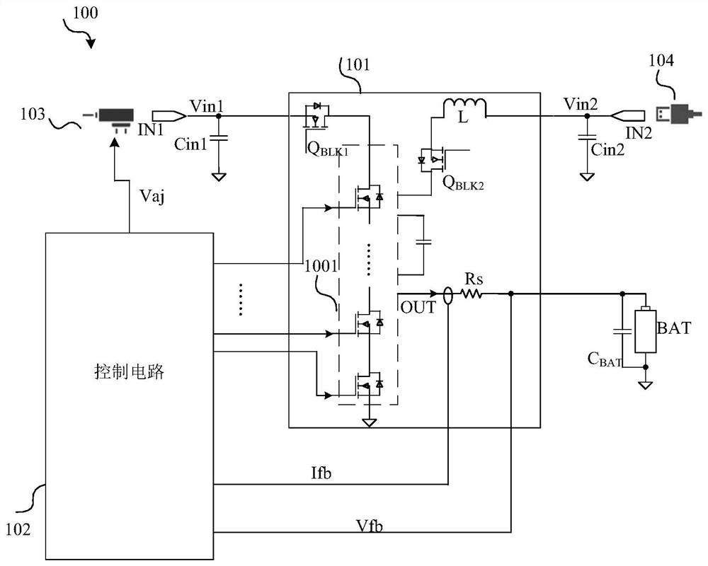
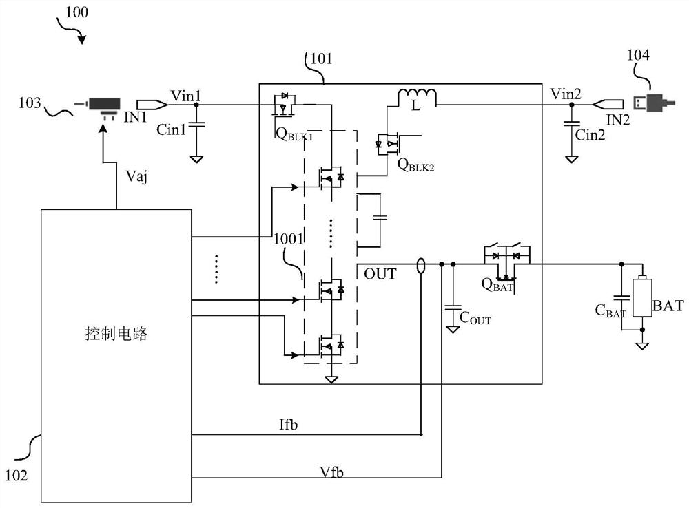
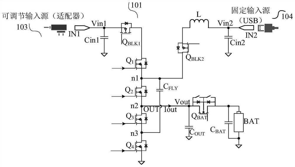
The invention discloses a charging circuit and a charging system thereof. The charging system includes a dual input charging circuit configured to operate in the form of a charge pump when the input is an adjustable voltage source and in the form of a hybrid switching converter when the input is a fixed voltage source to achieve higher efficiency. Meanwhile, the charger is provided with fewer power switches, so that the system cost is reduced.

Description

technical field [0001] The present invention relates to the technical field of power electronics, in particular to a charging circuit and a charging system for battery charging occasions. Background technique [0002] Batteries in portable devices can be charged from a variety of sources, including adapters and wireless power sources. A buck charger is a fairly common battery charger topology that converts an input DC voltage to generate a DC output voltage. A feedback loop is needed in the step-down charger to control the switching time of the power transistor in the circuit (that is, to adjust the duty cycle) in order to maintain the stable output current or voltage required for battery charging. However, in a buck charger, efficiency typically drops when the input voltage to the buck charger is much higher than the battery voltage. [0003] Charge pump circuits, also known as switched capacitor voltage converters, are more efficient than buck regulators when the input s...

Claims


Application Information

Patent Timeline
Patent Type & Authority Applications(China)
IPC IPC(8): H02J7/00H02M3/07H02M3/156
CPCH02J7/0045H02J7/00714H02J7/007182H02M3/07H02M3/156H02M3/158H02M3/1582H02J2207/20H02J1/10H02J2207/40H05B45/3725
Inventor 文司华卢钊
Owner NANJING SILERGY SEMICON TECH CO LTD
Features
  • R&D
  • Intellectual Property
  • Life Sciences
  • Materials
  • Tech Scout
  • Unparalleled Data Quality
  • Higher Quality Content
  • 60% Fewer Hallucinations
Learn More