
Charging pile for solar electric bicycle

A technology for solar electric bicycles and charging piles, applied in electric vehicle charging technology, electric vehicles, charging stations, etc., can solve the problems of damaged charging lines, theft by criminals, electric shock safety accidents, etc., to increase safety performance, guarantee Safety, the effect of increasing damping

Pending Publication Date: 2021-06-11
南京爱默升能源技术有限公司
View PDF0 Cites 0 Cited by
  • Summary
  • Abstract
  • Description
  • Claims
  • Application Information

AI Technical Summary

Problems solved by technology

[0002] Solar energy is a kind of renewable energy, which refers to the thermal radiation energy of the sun (see the three ways of heat energy transmission: radiation), the main performance is often called the sun's rays, and now people often convert solar energy into electrical energy and store it in batteries. It is used to charge electric vehicles. When charging, the charging wires are generally rolled up outside the charging pile, which is not only easy to be stolen by criminals, but also during normal use when the charger moves the charging head to the charging port of the solar motorcycle It may drag the wire, so that the wire will contact the ground during the moving process, and the contact with the ground for a long time will cause damage to the skin of the charging line, which may cause damage to the charging line and reduce the service life of the charging device. Electric shock accidents, and manual winding is required after charging is completed, which is very inconvenient

Method used


Image

  • Charging pile for solar electric bicycle
  • Charging pile for solar electric bicycle
  • Charging pile for solar electric bicycle

Examples


Embodiment 1

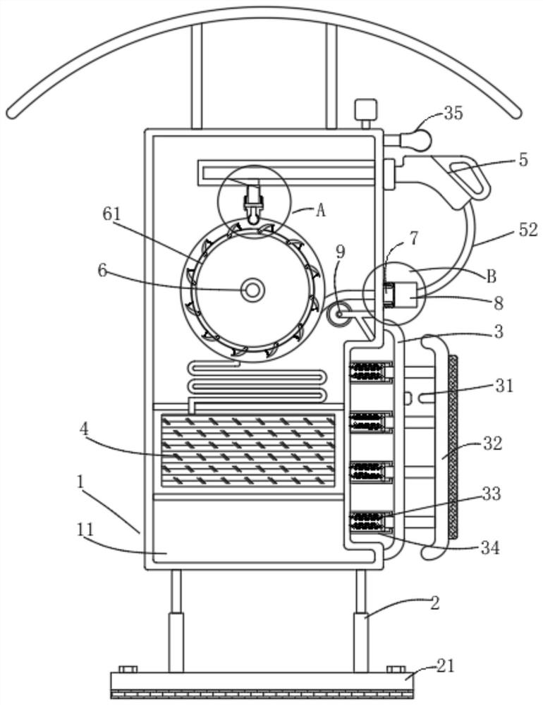
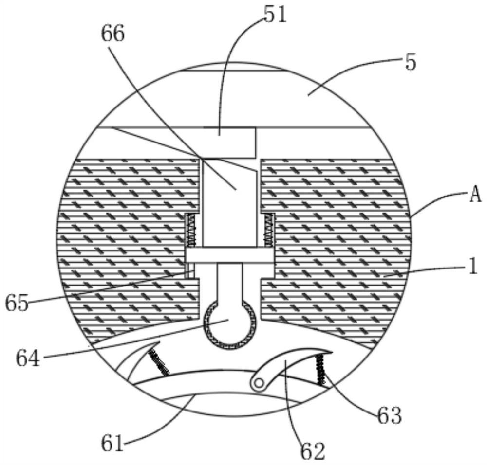
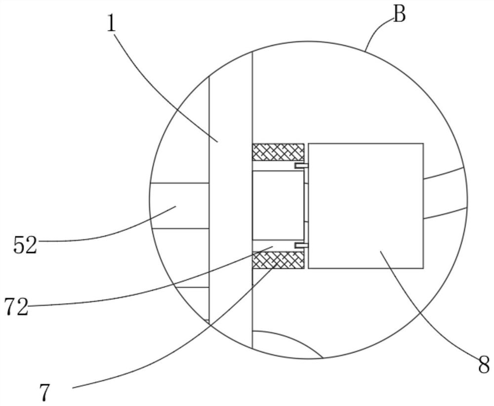
[0029] refer to Figure 1-4, a charging pile for solar electric bicycles, comprising a charging pile 1, a charging gun 5 and an automatic wire take-up mechanism, the automatic wire take-up mechanism includes a rotating shaft 6 arranged in the charging pile 1 and connected to it in rotation, on the rotating shaft 6 A torsion spring is provided so that the rotating shaft 6 is conveniently reset after being rotated by an external force. The rotating shaft 6 is wound with an electric wire 52 that is electrically connected to the storage box 4 provided in the charging pile 1, and the other end of the electric wire 52 runs through the charging The pile 1 is electrically connected with the charging gun 5, and the front and rear ends of the rotating shaft 6 are fixedly connected with decelerating rings 61, and the electric wires 52 are wound on the rotating shaft 6 between the decelerating rings 61, and the outer ring of the decelerating ring 61 is provided with an end The deceleratio...

Embodiment 2

[0034] refer to Figure 5-7 , a charging pile for solar electric bicycles. Compared with Embodiment 1, this embodiment also includes a skin wiping assembly arranged on the right side of the first fixed ring 7, and the skin wiping assembly includes a threaded ring 81 and the first fixed ring. The third fixed ring 8 that is threadedly connected to the ring 7, the inner ring of the third fixed ring 8 is fixedly connected with four evenly arranged installation blocks 82, and the wiper ring 83 is clamped on the installation block 82, and the wiper ring The inside of 83 is fixedly connected with a wiping layer 84, and the side of the third fixed ring 8 away from the first fixed ring 7 is fixedly connected with a twisted cover 85 through a threaded ring 81; working principle: when the electric wire 52 passes through the third fixed ring 8 The wiping layer 84 will wipe the surface to prevent the electric wire 52 from being contaminated with foreign matter on the surface of the chargin...

Embodiment 3

[0036] refer to figure 1 , a charging pile for solar electric bicycles. Compared with Embodiment 1, this embodiment further includes an anti-collision mechanism arranged on the right side of the charging pile 1, and the anti-collision mechanism includes a baffle arranged on the right side of the charging pile 1 3. An anti-collision plate 32 is provided on the right side of the baffle 3, and several fixing blocks 34 fixedly connected with the charging pile 1 are arranged between the baffle 3 and the charging pile 1, and the interior of the fixing blocks 34 The second slider is slidably connected to its inner wall, the second slider is elastically connected to the fixed block 34 through the first spring 33, and the second slider is fixedly connected to the anti-collision plate 32 through a connecting rod; Working principle: When the vehicle collides with the charging pile 1, the vehicle will first contact the anti-collision plate 32, and the second slider is driven by the connec...


PUM


Abstract

The invention discloses a charging pile for a solar electric bicycle, and relates to the technical field of charging piles. The charging pile comprises a charging pile, a charging gun and an automatic take-up mechanism, the automatic take-up mechanism comprises a rotating shaft arranged in the charging pile and rotationally connected with the charging pile, and the rotating shaft is provided with a torsion spring; a wire with one end electrically connected with an electricity storage box arranged in the charging pile is wound on the rotating shaft, the other end of the wire penetrates through the charging pile to be electrically connected with the charging gun, the front end and the rear end of the rotating shaft are fixedly connected with speed reduction rings, and the wire is wound on the rotating shaft between the speed reduction rings; and a speed reduction claw with one end hinged to the speed reduction ring is arranged on the outer ring of the speed reduction ring. According to the invention, through arrangement of the take-up mechanism, the electric wire can be always in a tightened state in the process of pulling out the electric wire during charging, the electric wire is prevented from being in contact with the ground, the safety performance of the device in the use process is improved, low-speed automatic winding can be realized after charging is completed, and use is convenient while the safety is ensured.

Description

technical field [0001] The invention relates to the technical field of charging piles, in particular to a charging pile for solar electric bicycles. Background technique [0002] Solar energy is a kind of renewable energy, which refers to the thermal radiation energy of the sun (see the three ways of heat energy transmission: radiation), the main performance is often called the sun's rays, and now people often convert solar energy into electrical energy and store it in batteries. It is used to charge electric vehicles. During charging, the charging wires are generally rolled up outside the charging pile, which is not only easy to be stolen by criminals, but also in the process of moving the charging head to the charging port of the solar motorcycle during normal use. It may drag the wire, so that the wire will contact the ground during the moving process, and the contact with the ground for a long time will cause damage to the skin of the charging line, which may cause damag...

Claims


Application Information

Patent Timeline
IPC IPC(8): B60L53/31H02G11/00F16F15/067
CPCB60L53/31F16F15/067H02G11/006Y02T10/70Y02T10/7072Y02T90/12
Inventor 张安爽陈林
Owner 南京爱默升能源技术有限公司
Features
  • Generate Ideas
  • Intellectual Property
  • Life Sciences
  • Materials
  • Tech Scout
  • Unparalleled Data Quality
  • Higher Quality Content
  • 60% Fewer Hallucinations
Learn More