Civil engineering seismic reduction device and seismic reduction method thereof

A shock absorbing device and civil engineering technology, which is applied in the direction of earthquake resistance, building components, building types, etc., can solve the problems of difficult repair of structures after earthquakes, economic losses of secondary components, etc., and achieve the effect of improving shock absorption and reducing losses

Inactive Publication Date: 2021-07-02
温州融宸科技有限公司
View PDF0 Cites 1 Cited by
  • Summary
  • Abstract
  • Description
  • Claims
  • Application Information

AI Technical Summary

Problems solved by technology

However, in the earthquakes in recent years, people have gradually realized that the traditional design method also has problems su

Method used


Image

  • Civil engineering seismic reduction device and seismic reduction method thereof
  • Civil engineering seismic reduction device and seismic reduction method thereof
  • Civil engineering seismic reduction device and seismic reduction method thereof

Examples


Example Embodiment

[0030] Example one

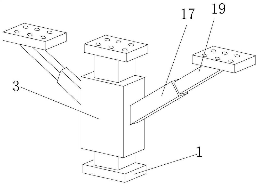
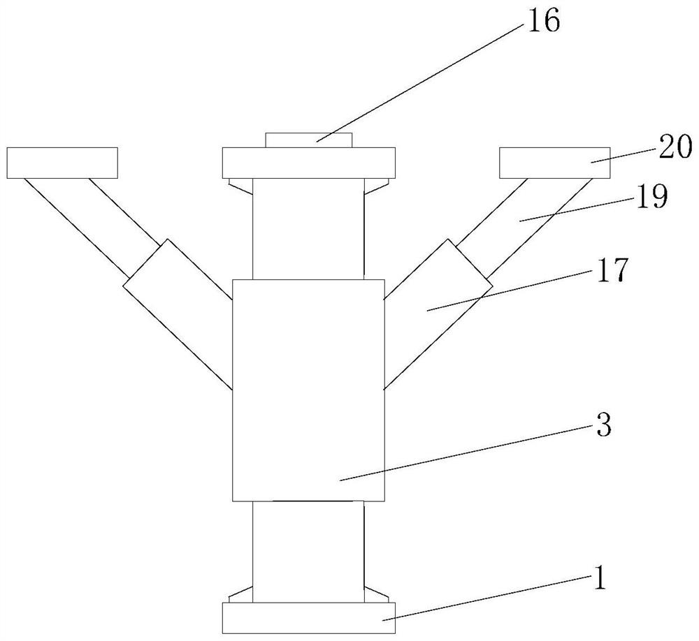
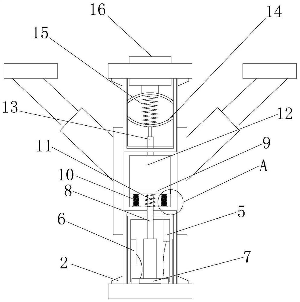
[0031] See Figure 1-6 , The present invention is provided: a civil engineering shock absorber device and a damper method thereof, including base 1, and the top of the base 1 is fixedly mounted with a reinforcing rib 2, the top of the base 1 is fixedly mounted with a protective box 3, protected The inside of the side wall of the cassette 3 is fixedly mounted having a buffer layer 4, and the inside of the protective case 3 is fixedly mounted, and the signal transmitter 5 is fixedly mounted, and the processor 6 is fixedly mounted, and the inside of the protective case 3 is fixedly mounted with gravity sensor 7. The top portion of the gravity sensor 7 is fixedly mounted, and the top portion of the transmitting rod 8 is fixedly mounted, and the bottom of the pressure sensor 9 is fixedly mounted, and the outer spring 10 is provided with a second spring 11. The top portion of the pressure sensor 9 is fixedly mounted having a buffer block 12, and the top portion of th...

Example Embodiment

[0040] Example 2

[0041] See Figure 1-6, The present invention is provided: a civil engineering shock absorber device and a damper method thereof, including base 1, and the top of the base 1 is fixedly mounted with a reinforcing rib 2, the top of the base 1 is fixedly mounted with a protective box 3, protected The inside of the side wall of the cassette 3 is fixedly mounted having a buffer layer 4, and the inside of the protective case 3 is fixedly mounted, and the signal transmitter 5 is fixedly mounted, and the processor 6 is fixedly mounted, and the inside of the protective case 3 is fixedly mounted with gravity sensor 7. The top portion of the gravity sensor 7 is fixedly mounted, and the top portion of the transmitting rod 8 is fixedly mounted, and the bottom of the pressure sensor 9 is fixedly mounted, and the outer spring 10 is provided with a second spring 11. The top portion of the pressure sensor 9 is fixedly mounted having a buffer block 12, and the top portion of the b...


PUM


Abstract

The invention discloses a civil engineering seismic reduction device and a seismic reduction method thereof. The civil engineering seismic reduction device comprises a base, reinforcing ribs are fixedly installed at the top of the base, a protection box is fixedly installed at the top of the base, a buffer layer is fixedly installed inside the side wall of the protection box, a signal transmitter is fixedly installed inside the protection box, a processor is fixedly installed on one side of the signal transmitter, a gravity sensor is fixedly installed inside the protection box, a transmission rod is fixedly installed at the top of the gravity sensor, a pressure sensor is fixedly installed at the top of the transmission rod, and a first spring is fixedly installed at the bottom of the pressure sensor. According to the civil engineering seismic reduction device and the seismic reduction method thereof, through cooperation of multiple groups of springs and dampers, earthquake energy is absorbed step by step, the seismic reduction effect is improved, and meanwhile, the sensors match to detect related physical quantities and send out detection signals, so that earthquake occurrence can be detected in time, and the earthquake level can be evaluated in time for response.

Description

technical field [0001] The invention relates to the technical field of civil engineering, in particular to a civil engineering damping device and a damping method thereof. Background technique [0002] The traditional seismic design of structures relies on the strength and deformation of the structure itself to resist earthquakes. Under small earthquakes, the structure is guaranteed to be in an elastic working state. When the structure is damaged under moderate and large earthquakes, the structural ductility is used to dissipate the seismic energy; at the same time, the structure After damage, the structural stiffness and natural vibration period decrease, and the input seismic energy decreases. The traditional ductility-based seismic design idea makes full use of the bearing capacity and deformation capacity of the structure itself, which is economical and has been widely used in the seismic codes of various countries in the world. However, in the earthquakes in recent yea...

Claims


Application Information

Patent Timeline
IPC IPC(8): E04B1/98E04H9/02
CPCE04B1/98E04H9/021
Inventor 饶金龙
Owner 温州融宸科技有限公司
Why Eureka
Try Eureka