Supercharge Your Innovation With Domain-Expert AI Agents!

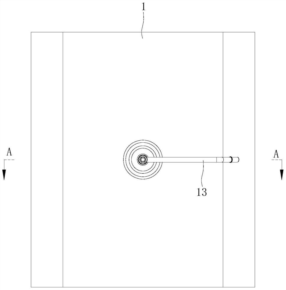
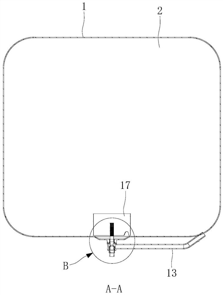
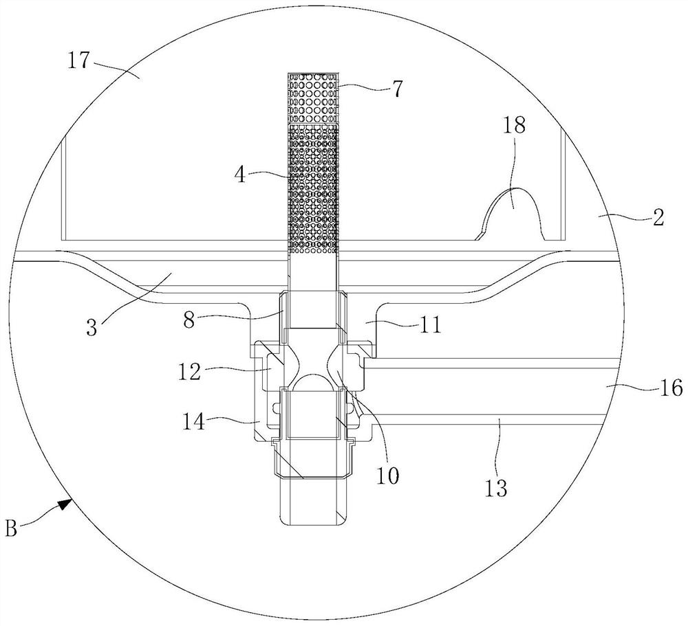
Fuel oil suction structure and automobile

A fuel oil and oil suction pipe technology, which is applied in the directions of liquid fuel feeders, engine components, machines/engines, etc., can solve the problems of redundant unusable volume and fuel cannot be sucked by the oil suction pipe, so as to improve the actual utilization rate and production. The effect of low debugging cost and low cost

Active Publication Date: 2021-07-02
DONGFENG LIUZHOU MOTOR
View PDF9 Cites 0 Cited by
  • Summary
  • Abstract
  • Description
  • Claims
  • Application Information

AI Technical Summary

Problems solved by technology

This structure leads to a certain redundant and unusable volume at the bottom of the fuel tank, and the fuel at the bottom of the fuel tank cannot be sucked by the suction pipe

Method used


Image

  • Fuel oil suction structure and automobile
  • Fuel oil suction structure and automobile
  • Fuel oil suction structure and automobile

Examples


Embodiment Construction

[0033] The specific implementation manners of the present invention will be further described in detail below in conjunction with the accompanying drawings and embodiments. The following examples are used to illustrate the present invention, but are not intended to limit the scope of the present invention.

[0034] In the description of the present invention, it should be understood that the terms "center", "upper", "lower", "front", "front" are used in the present invention. The orientations or positional relationships indicated by "rear", "vertical", "top", "bottom", "inner", "outer", etc. are based on the orientations or positional relationships shown in the drawings, and are only for the convenience of describing the present invention and simplified descriptions, rather than indicating or implying that the device or element referred to must have a specific orientation, be constructed and operate in a specific orientation, and thus should not be construed as limiting the in...


PUM


Abstract

The invention relates to the technical field of automobile machinery, and discloses a fuel oil suction structure and an automobile. The fuel oil suction structure comprises an oil tank and an oil suction pipe. The oil tank is provided with a cavity. A groove which is sunken downwards is formed in the bottom side of the cavity. The oil suction pipe is vertically arranged in the groove, and the bottom side of the oil suction pipe is connected to the bottom side of the cavity. A first oil delivering channel is formed in the oil suction pipe and extends in the axis direction of the oil suction pipe. A plurality of oil suction holes communicating with an oil delivering pipeline are formed in the upper portion of the oil suction pipe. A layer of filter net is arranged on the periphery of each oil suction hole. According to the fuel oil suction structure and the automobile, the volume utilization rate of the oil tank can be increased, and the production cost of the whole automobile is greatly reduced.

Description

technical field [0001] The invention relates to the technical field of automobile machinery, in particular to a fuel oil absorbing structure and an automobile. Background technique [0002] The current commercial vehicle diesel fuel tank is provided with an oil suction device. In order to prevent the oil suction pipe from inhaling impurities deposited on the bottom of the fuel tank, a gap of 10 mm to 15 mm is usually reserved between the bottom side of the oil suction pipe and the bottom side of the inner wall of the fuel tank. This structure causes the bottom of the fuel tank to always have a certain redundant and unusable volume, and the fuel at the bottom of the fuel tank cannot be sucked by the oil suction pipe. As the tank length is longer and the cross-sectional area is larger, the redundant volume is larger. Taking the 600-liter fuel tank currently used in the mainstream market as an example, the unusable volume at the bottom reaches about 43 liters. At present, th...

Claims


Application Information

Patent Timeline
IPC IPC(8): F02M37/00F02M37/50
CPCF02M37/0017F02M37/0076F02M37/50
Inventor 陈景林卓义盛潘宇飞许家毅林振贤朱永刚陆方伟
Owner DONGFENG LIUZHOU MOTOR
Features
  • R&D
  • Intellectual Property
  • Life Sciences
  • Materials
  • Tech Scout
  • Unparalleled Data Quality
  • Higher Quality Content
  • 60% Fewer Hallucinations
Learn More