Micro exhaust valve

A technology of micro-exhaust and vent holes, which is applied in the direction of valve details, valve devices, valve operation/release devices, etc., can solve the problems of small exhaust volume and cannot be enlarged, and achieve the effect of increasing exhaust volume

Pending Publication Date: 2021-07-02
ANHUI REDSTAR VALVE
View PDF14 Cites 0 Cited by
  • Summary
  • Abstract
  • Description
  • Claims
  • Application Information

AI Technical Summary

Problems solved by technology

[0003] The existing micro exhaust valve, the exhaust hole is restricted by the structure of th

Method used


Image

  • Micro exhaust valve
  • Micro exhaust valve
  • Micro exhaust valve

Examples


Example Embodiment

[0064] Example one

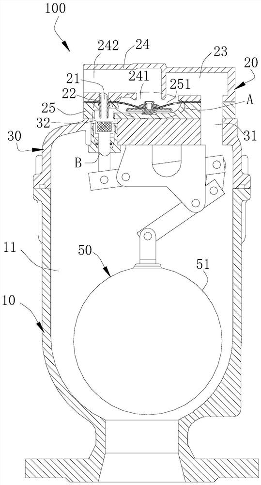
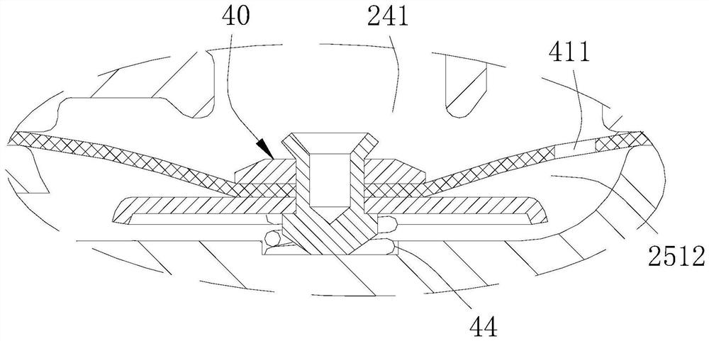
[0065] See figure 2 The spool assembly 40 includes a diaphragm 41, and the diaphragm 41 is provided between the first valve head 24 and the second valve head 25, and the diaphragm 41 is capable of blocking the main valve port 241, the diaphragm 41 cooperates with the second chamber 251. The communication chamber 2512 is formed, and the converging chamber 2512 is disposed away from the first passage 23 and the main valve port 241, and the communication chamber 2512 communicates with the first chamber 32, the damping hole 411 is opened on the diaphragm 41, and the first passage 23 passes the damping hole 411 and The connecting chamber 2512 is in communication, and the diaphragm 41 is located on the side of the side surface of the connecting cavity 2512 larger than the cross-sectional area of ​​the main valve port 241, so that in the case where the pressure balance between the diaphragm 41, the diaphragm 41 can be elastically becoming The direction of the main va...

Example Embodiment

[0072] Example 2

[0073] See Figure 5 The present embodiment is substantially the same as the structure of the embodiment, and the same is not described in the same, and the difference is:

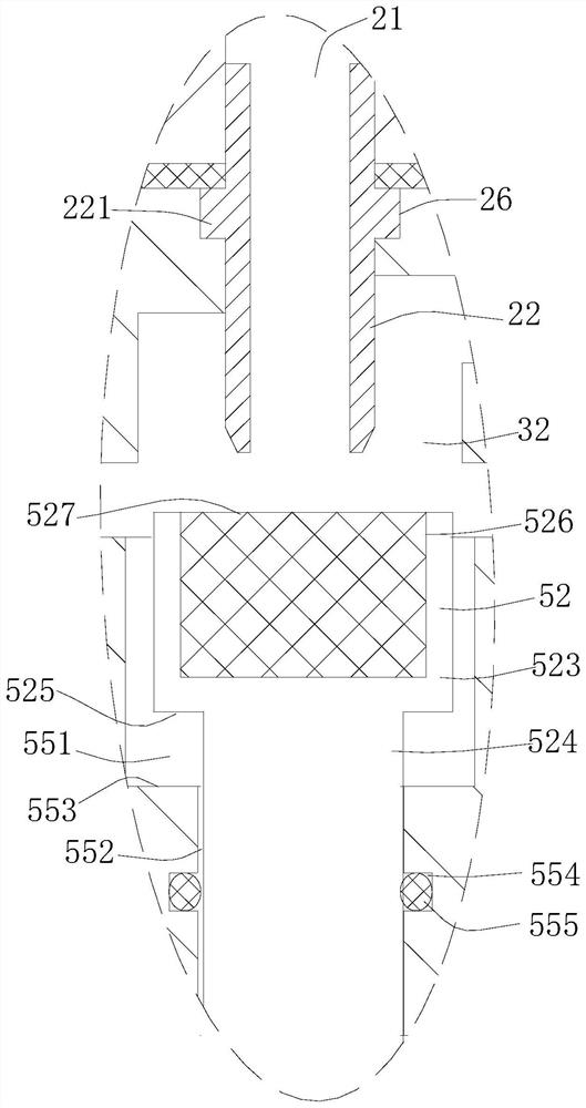
[0074] The spool assembly 40 includes a piston portion 45 and an elastic member 44, and the piston portion 45 is provided in the valve head assembly 20 and forms a connecting chamber 2512 with the valve head assembly 20, and one end of the elastic member 44 abuts the inner wall of the connecting cavity 2512. One end abuts against the piston portion 45, and the communication chamber 2512 can communicate or partition with the vent hole 21, and the piston portion 45 can move along the axial direction 2512 in the valve head assembly 20 to open or close the main valve port 241, the main The cross-sectional area of ​​the valve port 241 is smaller than the area of ​​the piston portion 45 toward the surface of the connecting chamber 2512. It is to be explained that the piston portion 45 here refers t...


PUM


Abstract

The invention relates to the field of valves, in particular to a micro exhaust valve. The micro exhaust valve comprises a valve body, a valve deck and a floater assembly, wherein a valve cavity is formed in the valve body; and an exhaust hole communicated with the outside is formed in the valve deck. The micro exhaust valve further comprises a valve head assembly and a valve element assembly arranged in the valve head assembly, wherein the valve head assembly is arranged at the end, away from the valve body, of the valve deck; the valve element assembly or the valve head assembly is provided with a damping hole communicating with the valve cavity; a main valve port communicates with the outside is formed in the valve head assembly; the caliber of the main valve port is larger than the caliber of the exhaust hole; when the floater assembly relieves blocking of the exhaust hole, the valve cavity communicates with the exhaust hole through the damping hole, and the valve element assembly can open the main valve port; and when the floater assembly blocks the exhaust hole, the valve element assembly can close the main valve port. The micro exhaust valve provided by the invention has the advantages that during exhaust, gas can be exhausted from the main valve port, so that the gas displacement is increased, and the gas displacement of the micro exhaust valve is not restrained by the lifting capacity of a floater any more.

Description

technical field [0001] The invention relates to the field of valves, in particular to a micro exhaust valve. Background technique [0002] The micro exhaust valve is installed in the piping system to remove the air in the piping system. [0003] In the existing micro-exhaust valve, the exhaust hole is restricted by the structure of the micro-exhaust valve itself, so it cannot be enlarged, and the exhaust volume is relatively small. Contents of the invention [0004] Based on this, the present invention aims at the above-mentioned technical problem, provides a kind of trace exhaust valve, technical scheme is as follows: [0005] A micro-exhaust valve, comprising a valve body, a valve cover and a float assembly, the valve body has a valve chamber, the valve cover is arranged on the valve body, and an exhaust port communicating with the outside is provided in the valve cover. hole, the float assembly is set in the valve cavity and can block the exhaust hole with the change ...

Claims


Application Information

Patent Timeline
IPC IPC(8): F16K31/12F16K31/20F16L55/07
CPCF16K31/12F16K31/20F16L55/07
Inventor 李维槽查从瑞马亮钟应武
Owner ANHUI REDSTAR VALVE
Why Eureka
Try Eureka