Supercharge Your Innovation With Domain-Expert AI Agents!

Guide rollers for printing machines

A technology of guide rollers for printing machines, applied to printing machines, rotary printing machines, general parts of printing machinery, etc. It can solve the problems of dirty printing patterns, blurred patterns of printing paper damage, curling, etc., and avoid slippage paper, improve fluency, improve stability

Active Publication Date: 2021-11-30
徐州拥森网络科技有限公司
View PDF0 Cites 0 Cited by
  • Summary
  • Abstract
  • Description
  • Claims
  • Application Information

AI Technical Summary

Problems solved by technology

In addition to these, printing products also need a series of auxiliary equipment, such as unwinding and winding devices, drying equipment, cooling equipment, tension control mechanisms, etc. These structures need to be realized by various guide rollers, among which tension balance control It is an extremely important part. If the tension balance is not well controlled, it will affect the printing efficiency and printing quality
[0003] However, in the long-term use of the existing guide roller structure, when the pattern on the surface of the printed paper is in direct contact with the main body of the guide roller for the printing machine, the printed pattern that has just come out and has not been dried and finalized is likely to be dirty by the main body of the guide roller for the printing machine. The pattern of the printed paper is damaged and blurred. In addition, during the paper transmission process, when the pattern cannot be in contact with the main body of the guide roller for the printing machine, paper jams will occur, and the paper will accumulate inside the printing equipment and cannot be exported or the paper will be curled. In view of this, the existing problems are studied and improved, and a guide roller for printing machines is provided to solve the existing problems. The purpose is to solve the problem and improve the practical value of the guide roller through this technology. Purpose

Method used


Image

  • Guide rollers for printing machines
  • Guide rollers for printing machines
  • Guide rollers for printing machines

Examples


Embodiment Construction

[0040]In order to make the object, technical solution and advantages of the present invention clearer, the present invention will be further described in detail below in combination with specific embodiments and with reference to the accompanying drawings. It should be noted that, in the case of no conflict, the embodiments of the present invention and the features in the embodiments can be combined with each other.

[0041] It is understood that these descriptions are exemplary only, and are not intended to limit the scope of the invention.

[0042] A guide roller for a printing machine provided by some embodiments of the present invention will be described below with reference to the accompanying drawings.

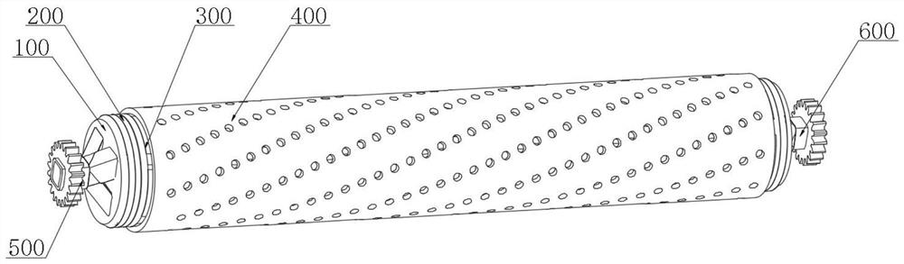
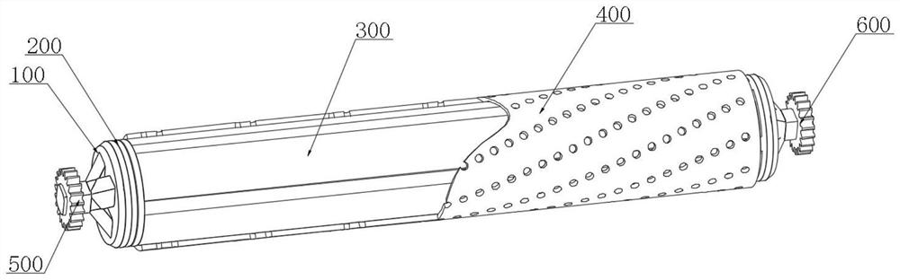
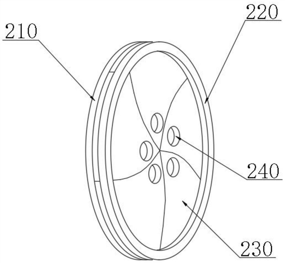
[0043] combine Figure 1-9 As shown, the guide roller for a printing machine provided by the present invention includes: a flange end plate 100, a tension adjustment mechanism 200, an expansion guide roller mechanism 300, and a conductive sleeve mechanism 400 fixedly sl...


PUM


Abstract

The invention discloses a guide roller for a printing machine, comprising: a flange end plate, a tension adjustment mechanism, an expansion guide roller mechanism, a conduction sleeve mechanism fixedly sleeved on the outside of the expansion guide roller mechanism, and a conductive sleeve mechanism fixedly installed on both sides and the flange. The first driving end ear and the second driving end ear fixedly connected to the end plate, the tension adjustment mechanism includes an outer driving ring, a fixed ring seat and an outer expansion ear plate, and the expansion guide roller mechanism includes several expansion bars, and several expansion bars The blocks are combined with each other to form a cylindrical structure. In the present invention, the outer expansion structure of the guide roller is set, and the outer expansion of the outer expansion ear plate can be realized through the non-synchronous operation of the outer drive rings at both ends during the working process of the guide roller by utilizing the torque transmission between the drive pin and the outer expansion ear plate movement, so as to drive the expansion bars of the expansion guide roller mechanism to expand and prop up the conductive sleeve mechanism, so that the diameter of the guide roller can be actively increased to fully contact the paper surface, avoiding the phenomenon of slipping and jamming, and improving printing quality. Output stability.

Description

technical field [0001] The invention relates to the technical field of printing machines, in particular to a guide roller for printing machines. Background technique [0002] A printing press is a machine for printing text and images. Its working principle is: first, the text and images to be printed are made into a printing plate, installed on the printing machine, and then the ink is applied to the printing plate by hand or by a printing machine. image, and then directly or indirectly transferred to paper or other substrates (such as textiles, metal plates, plastics, leather, wood, glass, and ceramics) to reproduce the same print as the printing plate, the invention of the printing press It plays an important role in the spread of human civilization and culture. In addition to these, printing products also need a series of auxiliary equipment, such as unwinding and winding devices, drying equipment, cooling equipment, tension control mechanisms, etc. These structures need...

Claims


Application Information

Patent Timeline
Patent Type & Authority Patents(China)
IPC IPC(8): B41F13/193B41F23/04B41F13/34
CPCB41F13/193B41F13/34B41F23/04
Inventor 王继林
Owner 徐州拥森网络科技有限公司
Features
  • R&D
  • Intellectual Property
  • Life Sciences
  • Materials
  • Tech Scout
  • Unparalleled Data Quality
  • Higher Quality Content
  • 60% Fewer Hallucinations
Learn More