Gas transmission snake-shaped robot
A snake-shaped robot and fluid transmission technology, applied in the field of bionic robots, can solve the problems of the snake-shaped robot being cumbersome, inflexible, and unable to move in the opposite direction, and achieve the effects of light weight, convenient transportation and flexible movement direction.
- Summary
- Abstract
- Description
- Claims
- Application Information
AI Technical Summary
Problems solved by technology
Method used
Image

Examples
specific Embodiment approach 1
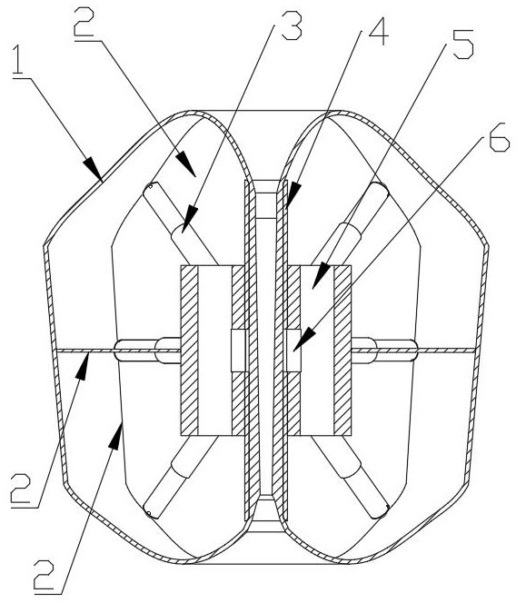
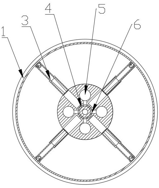
[0020] Specific implementation mode one: as Figure 1~Figure 2 As shown, the present invention discloses a gas-driven snake-like robot, which includes a flexible material bag 1, a partition gas membrane 2, a partition gas device 3, a retractable flexible bag cylinder 4, a charging and pumping gas drive device 5, and a belt drive device 6 ;
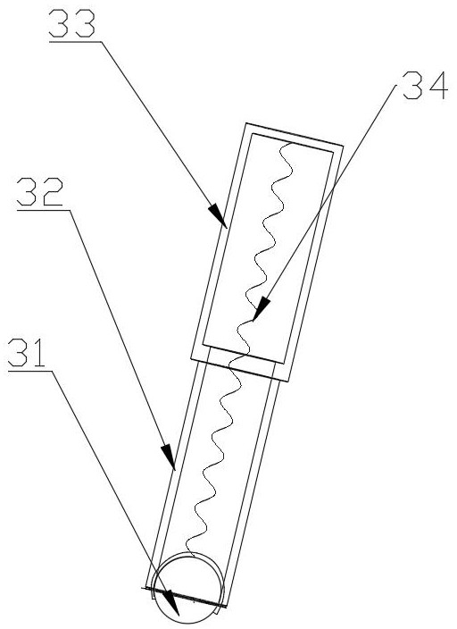
[0021] The outside of the gas-driven snake robot is surrounded by the flexible material bag 1. The flexible material bag 1 is made of a foldable flexible material, has a cylindrical shape and is sealed and filled with a certain amount of gas inside. The flexible material bag 1 The outer surface of the bag 1 has a certain frictional force, so that the gas transmission snake-shaped robot generates frictional force with the ground to convert it into a forward driving force. The flexible material bag 1 is composed of the head ball 31 and the inner Supported by gas, it passes through the retractable flexible bag cylinder 4 after folding and sh...
specific Embodiment approach 2
[0023] Specific implementation mode two: as Figure 4 , Figure 5 As shown, this embodiment is a further description of Embodiment 1. The charging and pumping gas driving device 5 includes a charging and pumping gas part device 51, and the charging and pumping gas part device 51 includes a cylinder 511, and the cylinder body 511 The upper end pressure vent 510 is made of rubber with a cross-shaped opening. When the charging and pumping gas drive device 5 is working, a large amount of gas is rushed into the cylinder 511 and the internal pressure is too high or a large amount of gas is drawn out. When it is too small, the pressure vent 510 is opened to discharge or fill the gas. The inside of the cylinder 511 includes a front baffle 513, a sealing rubber ring 516, and a rear baffle 517. The sealing rubber ring 516 is connected to the The inner wall of the cylinder body 511 is in contact, and the front baffle plate 513 and the rear baffle plate 517 leave a certain gap with the i...
specific Embodiment approach 3
[0026] Specific implementation mode three: as Figure 6 As shown, this embodiment is a further description of the second specific embodiment. The charging and pumping gas driving device 5 is characterized in that the charging and pumping gas driving device 5 includes a charging and pumping gas part device 51, a bar-shaped Gear 52, the tooth surface of described bar gear 52 is in contact with the tooth surface of two intermittent gears 53, and two described intermittent gears 53 are coaxial with driven gear 54 and driving gear 55 respectively, and described driving gear 55 passes shaft 56 links to each other with motor 57. Described motor 57 drives shaft 56, driving gear 55, intermittent gear 53 rotations, and driving gear 55 is externally meshed with driven gear 54, drives described driven gear and intermittent gear 53 to rotate, two described intermittent gears 53 and described The bar gear 52 is externally meshed so that the bar gear 52 reciprocates.
PUM
 Abstract
Description
Claims
Application Information
 - R&D
- Intellectual Property
- Life Sciences
- Materials
- Tech Scout
- Unparalleled Data Quality
- Higher Quality Content
- 60% Fewer Hallucinations
Browse by: Latest US Patents, China's latest patents, Technical Efficacy Thesaurus, Application Domain, Technology Topic, Popular Technical Reports.
© 2025 PatSnap. All rights reserved.Legal|Privacy policy|Modern Slavery Act Transparency Statement|Sitemap|About US| Contact US: help@patsnap.com