Supercharge Your Innovation With Domain-Expert AI Agents!

Shielding structure of connector assembly

一种组件、屏蔽壁的技术,应用在连接部件保护接地/屏蔽装置、连接装置的零部件、连接等方向,能够解决连接器性能降低等问题

Pending Publication Date: 2021-08-17
TAI LIAN SERVICES CO LTD
View PDF0 Cites 0 Cited by
  • Summary
  • Abstract
  • Description
  • Claims
  • Application Information

AI Technical Summary

Problems solved by technology

For example, gaps or spaces in the shielding that pass through a connector assembly can result in degraded connector performance

Method used


Image

  • Shielding structure of connector assembly
  • Shielding structure of connector assembly
  • Shielding structure of connector assembly

Examples


Embodiment Construction

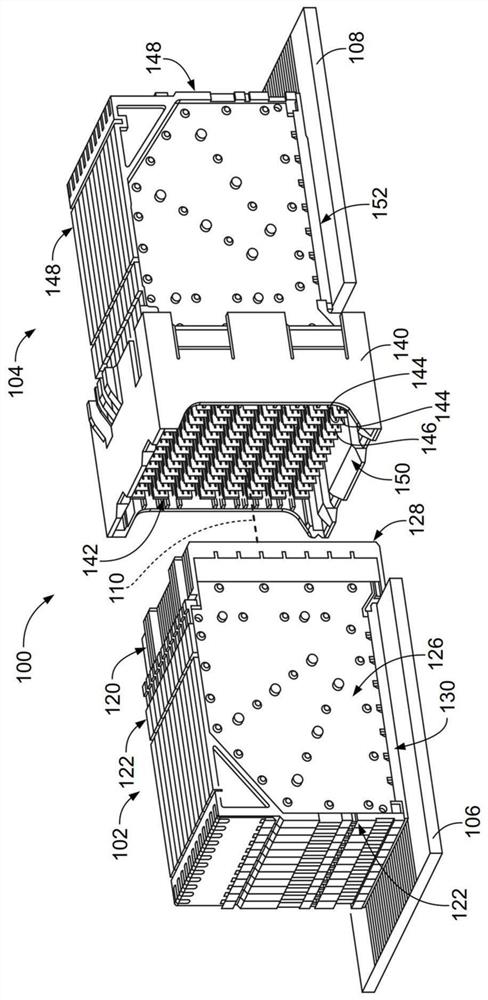
[0018] figure 1 is a perspective view of an exemplary embodiment of an electrical connector system 100 showing a first connector assembly 102 and a second connector assembly 104 that may be mated directly together. The first connector assembly 102 and / or the second connector assembly 104 may be referred to hereinafter individually as a "connector assembly" or collectively as a "connector assembly". The first connector assembly 102 is a receptacle assembly, and may hereinafter be referred to as the receptacle assembly 102 . The second connector assembly 104 is a header assembly and may be referred to as header assembly 104 hereinafter. The mating axis 110 extends through the first connector assembly 102 and the second connector assembly 104 . The first connector assembly 102 and the second connector assembly 104 are mated together in a direction parallel to and along the mating axis 110 .

[0019] In the exemplary embodiment, the first connector assembly 102 and the second c...


PUM


Abstract

A plug assembly (104) includes a plug housing (140) having a plug cavity (142). The plug assembly includes plug signal contacts (144) received in corresponding signal contact channels (162) having mating ends (154) disposed in the plug cavity for mating with the receptacle assembly (102). The header assembly includes header ground contacts (146) received in corresponding ground contact channels (164). Each plug ground contact includes a shielding wall forming a shielding cavity (190) that receives the plug signal contact to provide electrical shielding for the plug signal contact. The shield wall includes an end wall (170) extending between first and second sidewalls (172, 174). Each plug ground contact includes a mating projection (192) extending outwardly from a corresponding shield wall relative to the shield cavity. The mating projection is configured to engage a conductive insert (138) of the receptacle assembly for common potential of each of the plug ground contacts.

Description

technical field [0001] The subject of this article deals with connector components in general. Background technique [0002] Some electrical systems utilize connector assemblies, such as plug assemblies and socket assemblies, to interconnect two circuit boards, such as a motherboard and a daughter card. The connector assembly includes a contact module having contacts terminated to the circuit board. High-speed connector assemblies suffer from crosstalk issues and exhibit higher-than-expected insertion loss due to insufficient shielding. For example, gaps or spaces in the shielding of the pass-through connector assembly can result in degraded connector performance. [0003] There remains a need for cost effective and reliable shielding structures for electrical connector assemblies. Contents of the invention [0004] According to the present invention, a plug assembly is provided. The plug assembly includes a plug housing having a plug cavity between a mating end of the...

Claims


Application Information

Patent Timeline
Patent Type & Authority Applications(China)
IPC IPC(8): H01R13/629H01R13/652H01R13/6591H01R24/00
CPCH01R13/652H01R13/6591H01R13/629H01R24/00H01R13/6582H01R13/6587H01R12/735H01R13/6588H01R2107/00H01R13/428H01R13/506
Inventor D.A.特鲁特D.E.舍克J.B.麦克林顿J.D.皮克尔
Owner TAI LIAN SERVICES CO LTD
Features
  • R&D
  • Intellectual Property
  • Life Sciences
  • Materials
  • Tech Scout
  • Unparalleled Data Quality
  • Higher Quality Content
  • 60% Fewer Hallucinations
Learn More