A hybrid power transmission device for a new energy vehicle
A new energy vehicle, hybrid technology, applied in the direction of power device, transmission device parts, air pressure power device, etc., can solve the problems of no transmission device, single output shaft, heat dissipation, etc., and achieve the effect of stable transmission effect
- Summary
- Abstract
- Description
- Claims
- Application Information
AI Technical Summary
Problems solved by technology
Method used
Image
Examples
no. 1 example
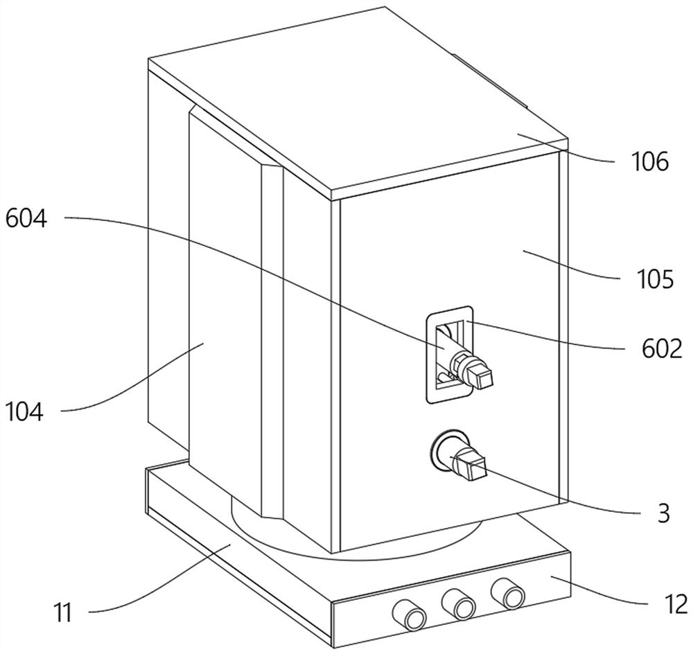
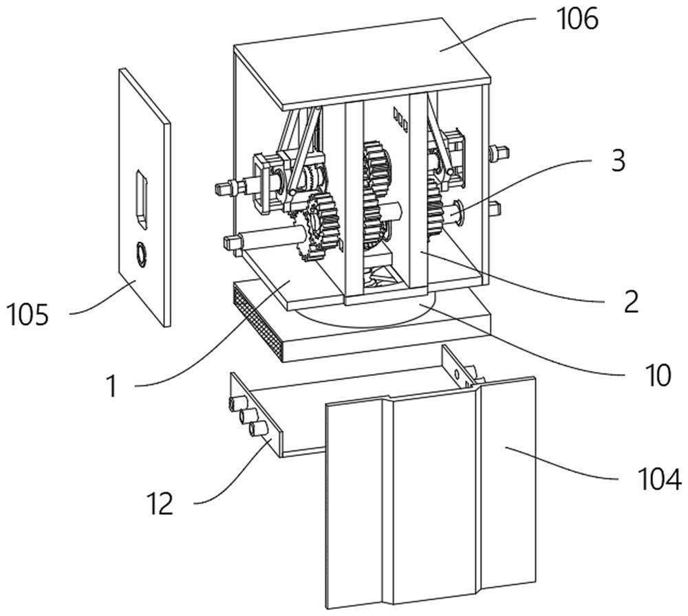
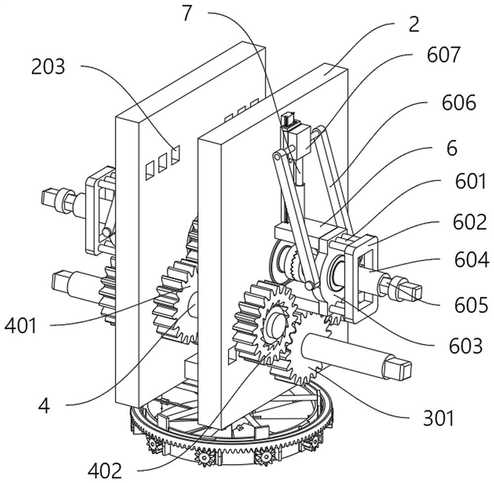
[0044] like Figure 1 to Figure 7 As shown, the present invention provides a hybrid power transmission device for a new energy vehicle, comprising: two sets of mounting frame plates 2 are fixedly arranged in the middle of the top of the main assembly seat 1; two sets of side plates are fixedly arranged on the sides of the main assembly seat 1 104 and two groups of end plates 105, the tops of side plates 104 and end plates 105 are fixedly provided with a top plate 106, and the side plates 104, end plates 105 and top plates 106 are all attached to the sides of the mounting frame plate 2; two groups of mounting frame plates 2 The power shaft 3 is arranged on the lower part of the center through the bearing rotation, and two sets of transmission gears 301 are fixedly arranged on the outside of the power shaft 3 relative to the two sets of mounting frame plates; Group linkage shaft 4; two sets of mounting frame plates 2 are provided with output shaft 5 through bearing rotation abov...
no. 2 example
[0055] Based on the hybrid power transmission device of a new energy vehicle provided in the first embodiment, the mounting base 6 also includes a connecting rod 606 and a slider 607; the two ends of the shaft seat 603 are provided with a connecting rod 606 through a hinge connection, and the connecting rod The other end of 606 is provided with slide block 607 through hinge connection rotation, and slide block 607 is arranged on the outside top of mounting frame plate 2 through guide rail sliding; Slide block 607 bottom is fixedly connected with electric cylinder 7 telescopic ends.
[0056] During the rotation of the power shaft 3, if it is necessary to quickly stop the transmission, the electric cylinder 7 can be directly contracted to move the connecting rod 606 and the slider 607 downward, and the electric cylinder 7, the connecting rod 606 and the slider 607 constitute a crank The slider mechanism can quickly move the shaft seat 603 outward, and during the process of the sh...
no. 3 example
[0060] Based on the hybrid transmission device of a new energy vehicle provided in the second embodiment, overheating and expansion caused by metal collision and contact may occur during the transmission process, which affects the transmission efficiency. The hybrid transmission device of a new energy vehicle is also Including: the outside of the transmission ring 8 is fixed with a fan frame 801 through a bracket, and the inside of the fan frame 801 is rotated with ten sets of rotating pieces 802. When the rotating pieces 802 are horizontal, they can be matched to form a ring. The middle pile 803; the outer ends of the rotating pieces 802 pass through the fan frame 801 and are fixedly provided with a conical adjustment gear 804; the top of the conical adjustment gear 804 is meshed with a ring gear 9, and the bottom of the ring gear 9 is welded with ten The group limit plate 901; the top of the ring gear 9 is provided with a semi-circular groove structure, and the pulley 103 is ...
PUM
 Abstract
Description
Claims
Application Information
 - R&D
- Intellectual Property
- Life Sciences
- Materials
- Tech Scout
- Unparalleled Data Quality
- Higher Quality Content
- 60% Fewer Hallucinations
Browse by: Latest US Patents, China's latest patents, Technical Efficacy Thesaurus, Application Domain, Technology Topic, Popular Technical Reports.
© 2025 PatSnap. All rights reserved.Legal|Privacy policy|Modern Slavery Act Transparency Statement|Sitemap|About US| Contact US: help@patsnap.com


