Target recognition device for industrial robot
An industrial robot and target recognition technology, which is applied in the field of target recognition devices of industrial robots, can solve problems such as short detection distance, inability to use flexibly, interference, etc.
- Summary
- Abstract
- Description
- Claims
- Application Information
AI Technical Summary
Problems solved by technology
Method used
Image

Examples
Embodiment 1
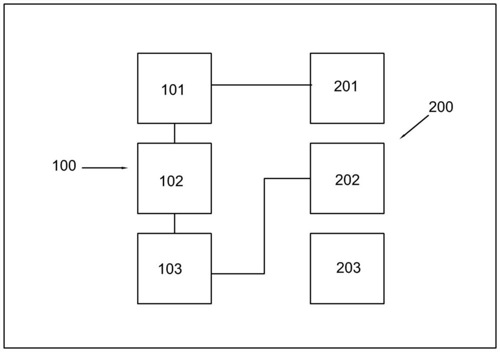
[0028] Refer figure 1 A target identification device for industrial robot, including, target acquisition assembly 100, including the camera 101 disposed at the front end of the robot, an information acquisition member 102 disposed inside the robot, and a processing member 103 electrically connected to the information acquisition member 102. The data storage component 200 includes an image processing member 201 electrically connected to the information acquisition member 102, a feedback command output 202 and information storage block 203 that are electrically connected to the image processing member 201; and adjustment assembly 300, the adjustment component 300 The rear end of the camera 101 is disposed.
[0029] Specifically, the main body structure of the present invention includes a target acquisition assembly 100, in the present embodiment, the target acquisition assembly 100 includes a camera 101 disposed at the front end of the robot, and the camera 101 is used to shoot the ...
Embodiment 2
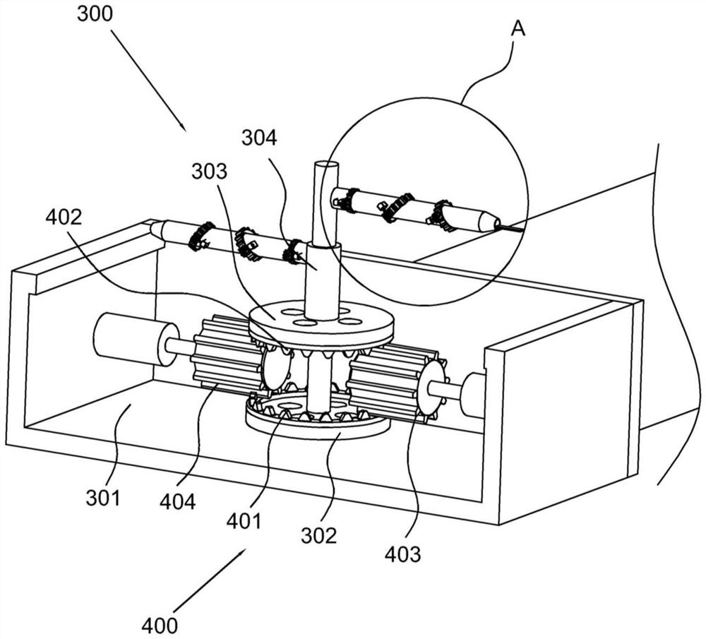
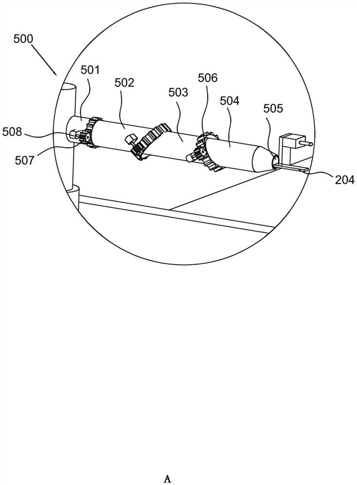
[0034] Refer figure 2 Sum image 3This embodiment is different from the first embodiment, and the camera is provided, and the connecting rod 204 is provided with a connecting rod 204, and the connecting rod 204 is provided with a turning piece 500, and the adjustment assembly 300 includes inside the robot. The storage groove 301 rotates the first rotation 302 connected to the storage slot 301 and the second rotary wheel 303 disposed with the first rotary wheel 302, and the rotation shaft of the first rotary wheel 302 extends vertically, the second A sleeve 304 set with the first rotary wheel 302 is provided, and a plurality of frames 304 are provided with a plurality of rods, and the upper end of the sleeve 304 is also provided with a number of frames, wherein the first A driver 400 is provided between the rotary 302 and the second rotary wheel 303, and the drive member 400 includes a first transfer 401 disposed at the edge of the first rotary wheel 302, which is disposed at the ed...
Embodiment 3
[0041] Refer Figure 4 The embodiment is different from the above embodiment, and the connection groove 505 is slipped to connect with the line 600, and the connecting rod 204 is inserted with the connecting groove 505, and the connection groove 505 is rotated and connected to the pendulum 601, the pendulor 601 lower end The lever 600 is hinged, and the connecting groove 505 is provided with a restricting cartridge 602 that cooperates with the lever 600, wherein the connection rod 204 is provided with a connecting ball 603, and the slot position of the connection groove 505 is provided with a cooperation with the connecting ball 603. The holes 604 are provided with a plurality of elastic members 605 and the fitting holes 604, and the rear end of the pendulum 601 is provided with a drive motor that is electrically connected to the processor.
[0042] Specifically, the lever 600 is connected to the connecting groove 505, and the connecting rod 204 is inserted with the connecting groo...
PUM
 Abstract
Description
Claims
Application Information
 - Generate Ideas
- Intellectual Property
- Life Sciences
- Materials
- Tech Scout
- Unparalleled Data Quality
- Higher Quality Content
- 60% Fewer Hallucinations
Browse by: Latest US Patents, China's latest patents, Technical Efficacy Thesaurus, Application Domain, Technology Topic, Popular Technical Reports.
© 2025 PatSnap. All rights reserved.Legal|Privacy policy|Modern Slavery Act Transparency Statement|Sitemap|About US| Contact US: help@patsnap.com