Defect detection method, device and system based on infrared thermal imaging
A technology for infrared thermal imaging and defect detection, applied in the field of optical detection, can solve the problems of low detection contrast and high resolution, improve the signal-to-noise ratio, overcome random fluctuations, and facilitate automatic detection and screening.
- Summary
- Abstract
- Description
- Claims
- Application Information
AI Technical Summary
Problems solved by technology
Method used
Image

Examples
Embodiment 1
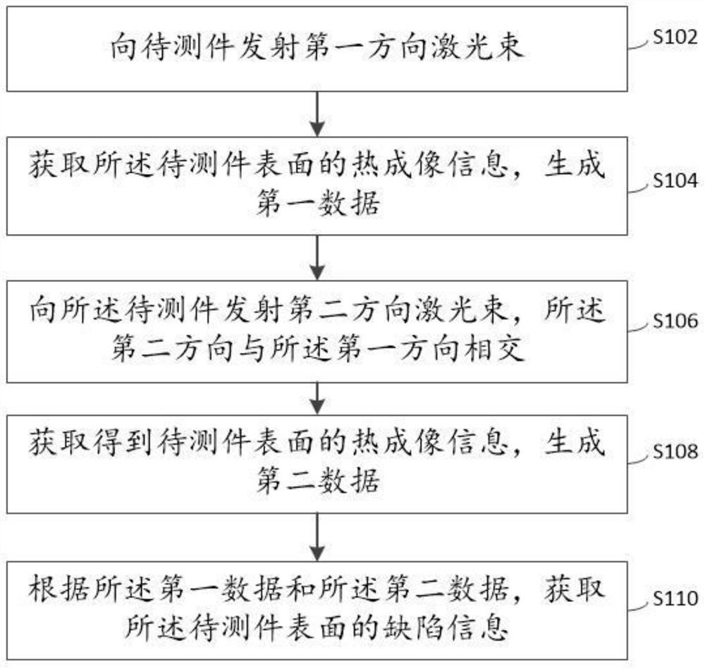
[0070] In order to comprehensively detect the surface and internal defects of the test piece and meet the requirements of high-precision detection, the embodiment of this specification provides a defect detection method based on infrared thermal imaging, specifically, as figure 1 As shown, the method includes the following steps:
[0071] S102: Emitting a laser beam in a first direction to the DUT;
[0072] The embodiment of this specification uses thermal imaging technology to achieve high-precision non-destructive testing. First, it is necessary to realize thermal excitation on the surface of the test piece, that is, to use the laser to test the area of the test piece. It should be noted that in order to improve the efficiency of thermal imaging reception, this implementation In the example, the irradiation direction of the laser beam in the first direction is at a certain angle with the object to be tested, and vertical incidence should be avoided. As an option, periodic ...
Embodiment 2
[0124] The embodiment of this specification provides a defect detection system based on infrared thermal imaging, which can realize the above-mentioned defect detection method based on infrared thermal imaging, specifically, as Figure 10 As shown, the system includes a laser 11 and a beam shaping module 12, the beam shaping module 12 is arranged at the light outlet of the laser 11, a beam splitter 13 is arranged in front of the beam shaping module 12, and the laser beam is divided into two by a beam splitting 13 mirrors. beam, so that the two beams of light are respectively irradiated on the left and right parts of the test piece 6 or two groups of test pieces 6 along two different directions, and the test piece 6 is arranged on the translation mechanism 8, and the translation mechanism 8 makes the The parts under test 6 move forward so that each group of parts under test 6 is irradiated by laser light in two different directions, and is detected by imaging with the infrared t...
Embodiment 3
[0129] On the basis of Embodiment 2, the embodiment of this specification provides a defect detection system based on infrared thermal imaging, which can realize the above-mentioned defect detection method based on infrared thermal imaging, specifically, as Figure 11 As shown, the difference between this embodiment and embodiment 2 is:
[0130] After the laser beams are split, they each pass through a beam retarder 141 and 142 and then irradiate the same DUT 6 , and no special translation mechanism needs to be provided under the DUT. By setting the respective delay time intervals of the beam retarders 141 and 142, the irradiation time of the two paths of light has a certain time difference Δt, so as to avoid mutual interference of laser excitation in two directions. For example, the light beam 111 is controlled by the beam retarder 141 at t 0 ~t 1 The light is emitted for a period of time, and then at an interval of Δt, the beam 112 is controlled by the beam retarder 142 at...
PUM
 Abstract
Description
Claims
Application Information
 - R&D
- Intellectual Property
- Life Sciences
- Materials
- Tech Scout
- Unparalleled Data Quality
- Higher Quality Content
- 60% Fewer Hallucinations
Browse by: Latest US Patents, China's latest patents, Technical Efficacy Thesaurus, Application Domain, Technology Topic, Popular Technical Reports.
© 2025 PatSnap. All rights reserved.Legal|Privacy policy|Modern Slavery Act Transparency Statement|Sitemap|About US| Contact US: help@patsnap.com