Check patentability & draft patents in minutes with Patsnap Eureka AI!

Elevated gantry machining tool

A technology for processing machine tools and gantry. It is applied in metal processing machinery parts, metal processing equipment, milling machines, etc. It can solve the problems of reducing the machining accuracy of machine tools and thermal displacement, and achieve the effect of strong adaptability and high efficiency.

Pending Publication Date: 2021-09-28
通用技术齐齐哈尔二机床有限责任公司
View PDF0 Cites 1 Cited by
  • Summary
  • Abstract
  • Description
  • Claims
  • Application Information

AI Technical Summary

Problems solved by technology

[0003] At present, the common ram of gantry machine tool adopts the structure of side hanging on the beam, which will cause thermal displacement (running center) of the spindle center of the machine tool due to the change of ambient temperature in the workshop, which reduces the machining accuracy of the machine tool

Method used


Image

  • Elevated gantry machining tool
  • Elevated gantry machining tool
  • Elevated gantry machining tool

Examples


Embodiment Construction

[0015] The present invention will be further described below in conjunction with accompanying drawing:

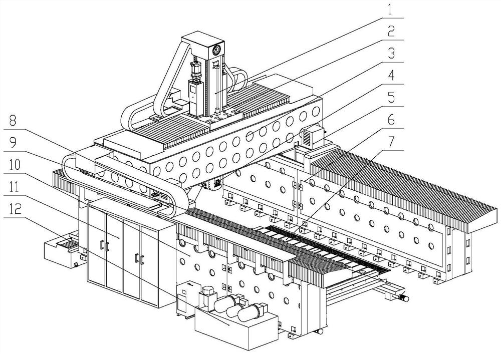
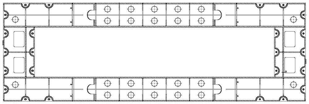
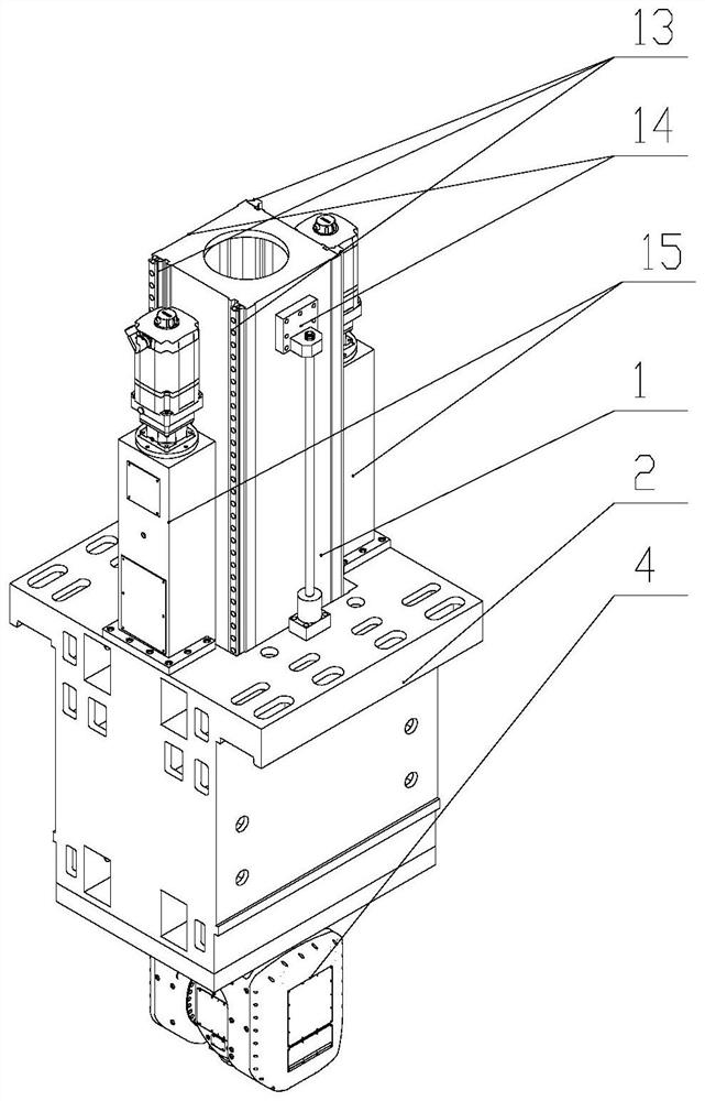
[0016] Depend on Figure 1 to Figure 4 As shown, an elevated gantry processing machine tool includes a left bed 10 and a right bed 6, and the left and right beds are fixed on the ground by anchor bolts to form the overall frame foundation of the machine tool. The left bed 10 is connected with a left slide 8 through the bed guide, and the right bed 6 is connected with a right slide 5 through the bed guide. The slide servo motor drives the left and right feed boxes through the reducer. , The right drive gear realizes the movement of the left and right sliding seats on the left and right bed. A crossbeam 3 is connected between the left slide 8 and the right slide 5 to form a gantry frame. The upper part of the crossbeam 3 is connected to the slide box 2 through the beam guide rail, and the slide box servo motor is fed through the slide box through the reducer. The box drives...


PUM


Abstract

The invention relates to an elevated gantry machining tool. The elevated gantry machining tool mainly solves the problem that a ram of an existing gantry machine tool is laterally hung on a cross beam, so that the center of a machine tool spindle is changed along with the change of the environment temperature to cause thermal displacement. The elevated gantry machining tool is characterized in that a left sliding seat (8) is connected to a left machine tool body (10) through a machine tool body guide rail, a right sliding seat (5) is connected to a right machine tool body (6) through a machine tool body guide rail, a cross beam (3) is connected between the left sliding seat (8) and the right sliding seat (5), the upper portion of the cross beam (3) is connected with a sliding box (2) through a cross beam guide rail, and a ram (1) in the vertical direction is connected to the center of the sliding box (2). According to the elevated gantry machining tool, a symmetrical cross beam structure is adopted, so that the thermal displacement caused by the change of the environment temperature of a workshop is reduced to the minimum, and the machining precision of the elevated gantry machining tool is improved.

Description

technical field [0001] The invention relates to the field of machine tools, in particular to an elevated gantry processing machine tool. Background technique [0002] The five-axis linkage CNC machine tool is a machine tool with high technological content and high precision, which is specially used for processing complex curved surfaces. Has a significant influence. High-end CNC machine tools represented by viaduct-type high-speed five-axis linkage machining centers are used in typical aircraft structural parts, aerospace complex and precise structural parts, and aviation missile engine parts. Key manufacturing equipment for national major special projects and key projects. [0003] At present, the common ram of gantry machine tool adopts the structure of side hanging on the beam, which will cause thermal displacement (running center) of the center of the machine tool spindle due to the change of ambient temperature in the workshop, which reduces the machining accuracy of ...

Claims


Application Information

Patent Timeline
IPC IPC(8): B23C1/00B23Q1/01B23Q5/40B23Q11/00
CPCB23C1/002B23Q1/012B23Q1/017B23Q1/015B23Q11/0042B23Q5/40
Inventor 高爱松王哲元江崇民吴志伟
Owner 通用技术齐齐哈尔二机床有限责任公司
Features
  • R&D
  • Intellectual Property
  • Life Sciences
  • Materials
  • Tech Scout
  • Unparalleled Data Quality
  • Higher Quality Content
  • 60% Fewer Hallucinations
Learn More