Supercharge Your Innovation With Domain-Expert AI Agents!

Dewatering well and dewatering construction method

A technology for dewatering wells and well bodies, applied in water/sewage treatment, chemical instruments and methods, water/sludge/sewage treatment, etc., can solve problems such as soil excavation and foundation pit support restrictions, affecting construction efficiency, etc. , to achieve the effect of reducing the number of well points and reducing the impact

Active Publication Date: 2021-10-01
泰州新润辰建设工程有限公司
View PDF6 Cites 0 Cited by
  • Summary
  • Abstract
  • Description
  • Claims
  • Application Information

AI Technical Summary

Problems solved by technology

[0006] In view of the above-mentioned related technologies, the inventor believes that the number of well points arranged around the foundation pit is relatively large, which limits the excavation of the soil and the support of the foundation pit during the construction of the foundation pit, which affects the construction efficiency

Method used


Image

  • Dewatering well and dewatering construction method
  • Dewatering well and dewatering construction method
  • Dewatering well and dewatering construction method

Examples


Embodiment 1

[0072] The embodiment of the present application discloses a dewatering well.

[0073] refer to figure 1 , the dewatering well includes at least one well body, and all the well bodies are connected and installed at the same well point.

[0074] In this embodiment, there is only one well body, and the well body includes at least three well body pipes 4, of which the lowermost one well body pipe 4 is a sedimentation pipe 2 installed in a confined aquifer 12; all other well body pipes 4 The filter pipe 3 runs through the submerged aquifer 11 , the aquifer 13 and the confined aquifer 12 .

[0075] refer to figure 1 , the bottom wall of the sedimentation tube 2 is sealed, and the opening faces upward. The water filter pipe 3 is a through pipe connected up and down, and the inner diameter of the water filter pipe 3 is consistent with that of the sedimentation pipe 2 .

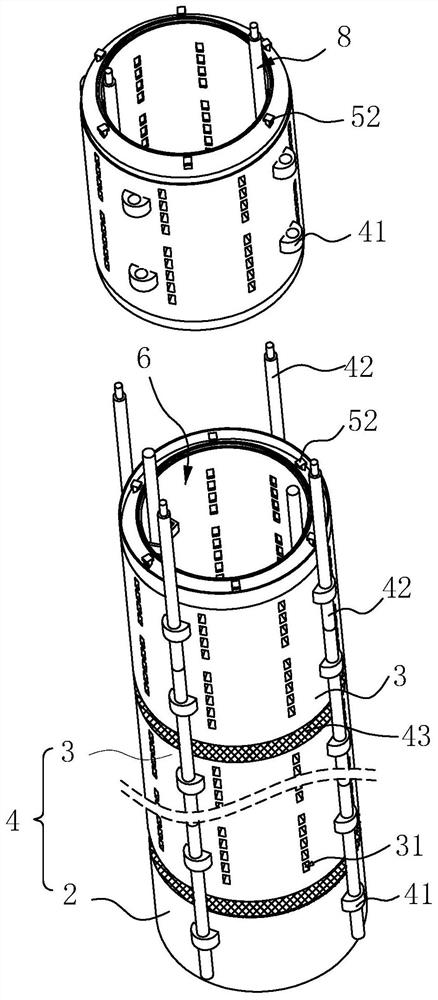
[0076] refer to figure 2 , each well body pipe 4 is provided with a collar 41 , and an outer connecting rod ...

Embodiment 2

[0103] The application discloses a precipitation well.

[0104] refer to Figure 7 , based on Embodiment 1, the difference between this embodiment and Embodiment 1 is that the structure of the control mechanism 7 is different.

[0105] refer to Figure 4 , Figure 7 , in this embodiment, the push ring 71 is provided with a notch 72 for the connecting assembly 8 to snap into the push ring 71 along a direction perpendicular to the axial direction of the push ring 71 .

[0106] The upper end of the fixing rod 81 can extend to the same horizontal position as the push ring 7 , and penetrate into the push ring 71 through the notch 72 . The inner wall of the push ring 71 has a rotation range for the fixed rod 81 to rotate axially around the water filter pipe 3 to cover or communicate with the water filter hole 31 , and the rotation range corresponds to the disassembly arc.

[0107] The notch 72 can be located on the side of the push ring 71 away from the inner wall of the water f...

Embodiment 3

[0112] The application discloses a precipitation well.


PUM


Abstract

The invention relates to the technical field of dewatering construction, and particularly relates to a dewatering well and a dewatering construction method. The dewatering well penetrates through a diving aquifer and a confined aquifer and comprises a sedimentation pipe and a water filtering pipe, wherein the water filtering pipe is provided with a shielding piece used for shielding a water filtering hole; the shielding piece is controlled by a control mechanism to select whether to shield the water filtering hole or not, so that underground water located on the upper portion is preferentially drained in the dewatering well, the dewatering well is matched with the construction depth of a foundation pit, and blocking of the underground water aquifer due to the influence of a water-resisting layer is reduced; and meanwhile, the number of well points of the dewatering well or a drainage well is effectively reduced, and the influence on foundation pit construction is reduced. The dewatering construction method comprises the construction steps of well pipe descending, filter material landfill, dewatering completion pipe drawing, dewatering well washing and the like, whether the water filtering pipe communicates with the interior and the exterior of the water filtering pipe or not can be selected by means of the shielding piece, whether the dewatering well communicates with the water level of the corresponding underground water or not is controlled, and whether the shielding piece shields the water filtering pipe or not can be selected and controlled conveniently according to the foundation pit construction requirements.

Description

technical field [0001] The present application relates to the technical field of dewatering construction, in particular to a dewatering well and a dewatering construction method. Background technique [0002] When carrying out deep foundation pit construction in an area with a high groundwater level, because the aquifer of the soil is cut off and affected by the pressure difference, groundwater will continuously infiltrate into the foundation pit, which will be unfavorable to the foundation pit construction. [0003] Moreover, the groundwater layer in the same area often has multiple aquifers at the same time, and different aquifers may be separated by rock formations or other geology, forming a shallow unconfined aquifer and a deep confined aquifer separated by an aquifer. The phreatic aquifer is located on the surface and is mainly affected by the flow of the terrain; the confined aquifer is located between the aquifers and has a certain pressure. When the upper aquifer is...

Claims


Application Information

Patent Timeline
Patent Type & Authority Applications(China)
IPC IPC(8): E02D19/10E02D19/22E03F5/04E03F5/14
CPCE02D19/10E02D19/22E03F5/0404E03F5/14
Inventor 刘俊李如飞
Owner 泰州新润辰建设工程有限公司
Features
  • R&D
  • Intellectual Property
  • Life Sciences
  • Materials
  • Tech Scout
  • Unparalleled Data Quality
  • Higher Quality Content
  • 60% Fewer Hallucinations
Learn More