Colored paper cutting equipment for gift box packaging
A packaging and gift box technology, applied in metal processing and other directions, can solve the problems of low safety, accidental blade injury, affecting work efficiency, etc., and achieve the effect of high safety, avoiding movement, and consistent length
- Summary
- Abstract
- Description
- Claims
- Application Information
AI Technical Summary
Problems solved by technology
Method used
Image

Examples
Embodiment 1
[0075] A kind of colored paper cutting equipment for gift box packaging, such as Figure 1-Figure 7 As shown, it includes a base 1, a worktable 2, a cutter 3, a cutting mechanism 4, a clamping mechanism 5, and a positioning mechanism 6. The top of the base 1 is provided with a workbench 2, and the front and rear sides of the workbench 2 are opened on the right. A plurality of round holes, a cutting mechanism 4 is provided on the left side of the top of the workbench 2, a cutter 3 is provided on the cutting mechanism 4, a clamping mechanism 5 is provided on the cutting mechanism 4, and a positioning mechanism is provided on the right side of the workbench 2 6.
[0076] The cutting mechanism 4 includes a first mounting frame 41, a first guide rod 42, a sliding frame 43, an electric push rod 44 and a pull bar 45. The left side of the top of the workbench 2 is provided with a first mounting frame 41, and inside the first mounting frame 41 Front and rear symmetry is provided with ...
Embodiment 2
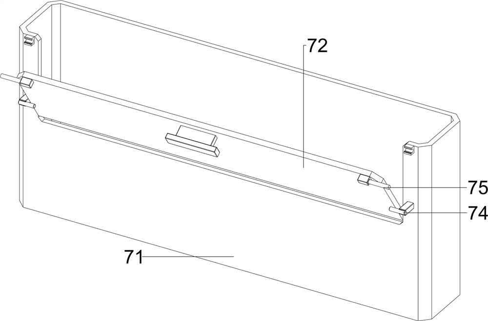
[0081] On the basis of Example 1, such as figure 1 , Figure 8 , Figure 9 and Figure 10 As shown, a collection mechanism 7 is also included, and the collection mechanism 7 includes a collection frame 71, a first baffle plate 72, a handle 73, a limit rod 74, a second clamp rod 75 and a clamp block 76, and the top left side of the base 1 is provided with Collecting frame 71, the left middle part of collecting frame 71 is rotatably provided with first baffle plate 72, and the middle of the left upper part of first baffle plate 72 is provided with handle 73, and collecting frame 71 left side upper part is symmetrically provided with limit lever 74 front and back, and the limit Rod 74 cooperates with the first baffle plate 72, and the first baffle plate 72 upper left side is symmetrically provided with the second clamping rod 75 front and back, and the collection frame 71 left side upper part is provided with clamping block 76 symmetrically, the clamping block 76 and the second...
Embodiment 3
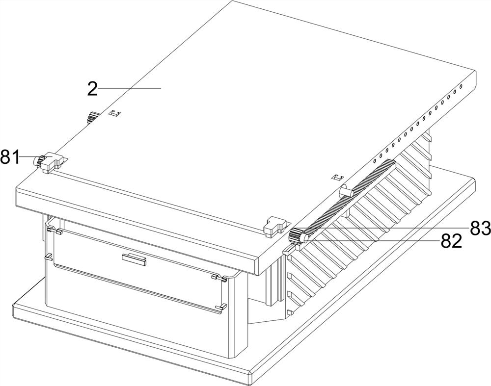
[0084] On the basis of Example 2, such as figure 1 ,and Figure 11-Figure 17 As shown, a safety mechanism 8 is also included. The safety mechanism 8 includes a second baffle plate 81, a rotating rod 82, a first gear 83 and a first rack 84. The left side of the workbench 2 is slidably provided with a second baffle plate 81. , the left side of the workbench 2 is provided with a rotating rod 82, and the rotating rod 82 is located on the right side of the second baffle plate 81. The first rack 84 is meshed with the first gear 83 .
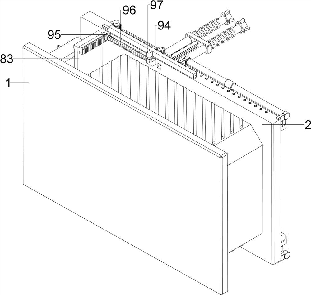
[0085] Also comprise lifting mechanism 9, and lifting mechanism 9 comprises the 3rd spring 91, push plate 92, guide rail 93, the 2nd tooth bar 94, the 4th guide bar 95, the 4th spring 96, connecting block 97, the 3rd tooth bar 98 and the second gear 99, between the two first guide rods 42 middle parts on the same lateral side, a push plate 92 is slidably arranged, and the push plate 92 cooperates with the sliding frame 43, and the first guide rod 42 ...
PUM
 Abstract
Description
Claims
Application Information
 - R&D
- Intellectual Property
- Life Sciences
- Materials
- Tech Scout
- Unparalleled Data Quality
- Higher Quality Content
- 60% Fewer Hallucinations
Browse by: Latest US Patents, China's latest patents, Technical Efficacy Thesaurus, Application Domain, Technology Topic, Popular Technical Reports.
© 2025 PatSnap. All rights reserved.Legal|Privacy policy|Modern Slavery Act Transparency Statement|Sitemap|About US| Contact US: help@patsnap.com