Engineering surveying pay-off device
A pay-off device and engineering measurement technology, applied in the directions of measuring devices, measuring instruments, surveying and navigation, etc., can solve the problems of inconvenient operation, uneven winding, lack of pay-off equipment, etc., to get rid of uneven winding, compact effect
- Summary
- Abstract
- Description
- Claims
- Application Information
AI Technical Summary
Problems solved by technology
Method used
Image

Examples
Embodiment 1
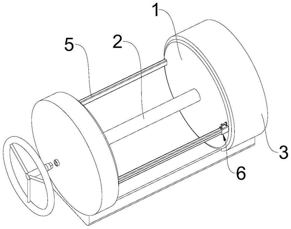
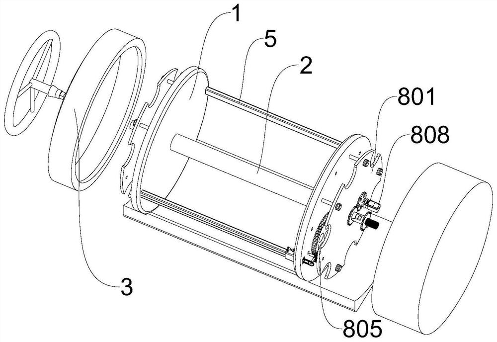
[0027] see Figure 1-3 , a kind of engineering measurement pay-off device, comprises a kind of engineering measurement pay-off device, comprises wire reel 1, rotating shaft A2, fixed cover 3, two wire reels 1 are left and right symmetrically arranged, and rotating shaft A2 is arranged between two wire reels 1 And hollow setting, the fixed cover 3 is fixed on the outer side of the wire reel 1 and forms a closed space with it, the middle part of the rotating shaft A2 is provided with a rotating shaft B4 that both ends pass through the wire reel 1 and extend to the inside of the fixed cover 3 respectively, between the two wire reels 1 There are two limit rods 5 parallel to the rotating shaft A2, one of the limit rods 5 is provided with a wire mechanism 6, a manual adjustment mechanism 7 is provided inside the fixed cover 3 on the left, and a manual adjustment mechanism 7 is located inside the fixed cover 3 on the right. A driving mechanism 8 is provided.
[0028] The part where ...
Embodiment 2
[0031] see Figure 5 , based on Embodiment 1, the difference is that the wire mechanism 6 includes a support base 601 and a wire base 602, and the right end of the limit rod 5 passes through the wire tray 1 on the right side and extends to the inside of the right fixed cover 3 and is hollow. Set, the inside of the limit rod 5 is symmetrically provided with two chute 603, the inside of the chute 603 is provided with a slider 604, the position of the limit rod 5 is horizontally provided with a limit hole 605 along the position of the middle part of the chute 603, and the outside of the slide block 604 The end is fixed with a guide rod 606 extending to the outside of the limit rod 5 , the guide rod 606 is plugged into the inside of the support seat 601 and fixed thereto, and the wire seat 602 is fixed to the top surface of the support seat 601 .
[0032] The wire mechanism 6 also includes a sprocket A607, a chain A608, a sprocket B609, and a chain B610. The two sprockets A607 and t...
Embodiment 3
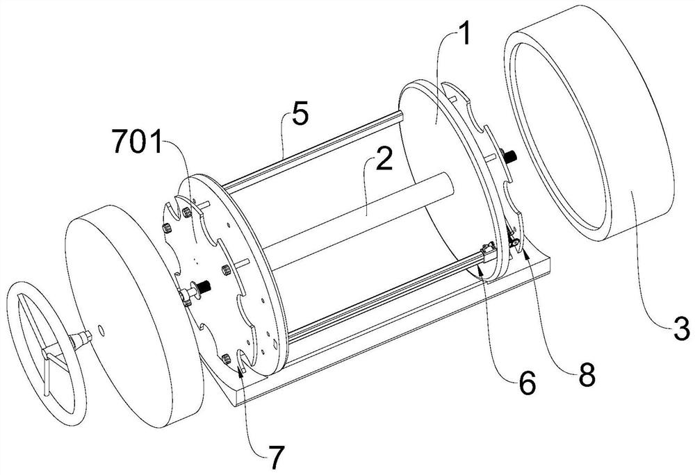
[0037] see Figure 3-4 , based on Embodiment 1-2, the difference is that the manual adjustment mechanism 7 includes a limit plate A701, the limit plate A701 is fixed in the middle of the fixed cover 3 on the left, and the left end of the rotating shaft B4 extends through the fixed cover 3 to its On the left side, a spring A702 fixed to the limiting plate A701 is provided on the outside of the rotating shaft B4. A limiting groove 703 is provided in the middle of the fixed cover 3 on the left side, and a rectangular groove 704 extending to the limiting groove 703 is fixed on the rotating shaft B4.
[0038] The present invention provides a limit groove 703 in the middle part of the fixed cover 3 on the left side, and the rotating shaft B4 extends to the left until near the limit groove 703 and fixes a rectangular groove 704 at its left end. A spring A702 is provided on the left side of the plate A701. The spring A702 extends to the left along the outer side of the rotating shaft ...
PUM
 Abstract
Description
Claims
Application Information
 - R&D
- Intellectual Property
- Life Sciences
- Materials
- Tech Scout
- Unparalleled Data Quality
- Higher Quality Content
- 60% Fewer Hallucinations
Browse by: Latest US Patents, China's latest patents, Technical Efficacy Thesaurus, Application Domain, Technology Topic, Popular Technical Reports.
© 2025 PatSnap. All rights reserved.Legal|Privacy policy|Modern Slavery Act Transparency Statement|Sitemap|About US| Contact US: help@patsnap.com