
Anesthetic needle

A technology of anesthesia needles and syringes, applied in the field of anesthesia needles, which can solve the problems of sharp anesthesia needles, puncture medical staff, and poor safety, and achieve the effect of easy use and storage, and improved safety

Active Publication Date: 2021-11-02
胡蓉
View PDF4 Cites 1 Cited by
  • Summary
  • Abstract
  • Description
  • Claims
  • Application Information

AI Technical Summary

Problems solved by technology

[0004]Injection anesthesia uses anesthesia needles to inject anesthetics. Currently, when injecting anesthesia, the anesthesia needle and the syringe are separated, and the anesthesia needle and needle need to be separated during injection. After the injection, the anesthesia needle and the syringe are collected separately. When collecting the anesthesia needle, the anesthesia needle is relatively sharp, which may hurt the medical staff. The safety is poor and the storage is inconvenient.

Method used


Image

  • Anesthetic needle
  • Anesthetic needle

Examples


Embodiment

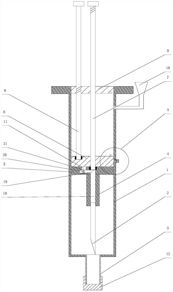
[0024] Such as figure 1 As shown, an anesthesia needle is provided in this embodiment, including a syringe 1 and a needle head 2, the top of the syringe 1 is closed by a closing plate 9, and the bottom of the syringe 1 has a needle hole, and the needle hole Connected to the outlet cylinder 3, the first piston 5 and the second piston 6 are all arranged in the needle cylinder 1, the first piston 5 and the second piston 6 are connected with the inner wall of the needle cylinder 1 in a sliding seal, the second piston 6 is located above the first piston 5, the top of the first piston 5 is connected with the first piston rod 7, the first piston rod 7 moves through the second piston 6 and the closing plate 9, between the first piston rod 7 and the second piston 6 Sliding seal, the top of the second piston 6 is connected with the second piston rod 8, the second piston rod 8 moves through the closing plate 9, the needle head 2 is fixed on the needle handle 4, and the needle handle 4 is...

Embodiment 2

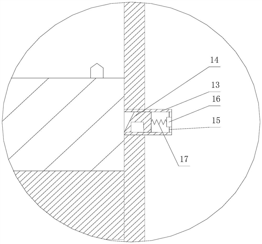
[0030] This embodiment is further limited on the basis of Embodiment 1. In this embodiment, the side wall of the syringe 1 is provided with a through hole, the through hole is connected with a containing tube 13, and the inner cavity of the containing tube 13 is in the shape of a cuboid , a blocking block 14 is slidably arranged in the containing tube 13, and the blocking block 14 can completely close the left end of the containing tube 13, and a fixing plate 16 is fixed in the containing tube 13 by a connecting rod 15, and the left wall of the fixing plate 16 is in contact with the blocking block 14. The right walls are connected by the first spring 17, and the left wall of the blocking block 14 is inclined downward as a whole in the direction from right to left. In the initial state, the second piston 6 is against the blocking block 14, so that the blocking block 14 is positioned at the receiving tube. 13, the first spring 17 is in a compressed state;

[0031] A liquid inlet...


PUM


Abstract

The invention discloses an anesthetic needle which comprises a needle cylinder and a needle head, the top end of the needle cylinder is sealed through a sealing plate, a needle outlet hole is formed in the bottom end of the needle cylinder, a needle outlet cylinder is connected to the needle outlet hole, a first piston and a second piston are both arranged in the needle cylinder, and the top end of the first piston is connected with a first piston rod; the first piston rod movably penetrates through the second piston and the sealing plate, the first piston rod and the second piston are in sliding sealing, the top end of the second piston is connected with a second piston rod, the second piston rod movably penetrates through the sealing plate, the needle head is fixed to the needle handle, the needle handle is fixed to the bottom wall of the first piston, and a liquid outlet hole is formed in the first piston. A circulation channel is formed in the needle handle, the circulation channel is communicated with the liquid outlet hole and the needle head, liquid above the first piston can be discharged through the liquid outlet hole, the circulation channel and the needle head, the needle head is located in the needle cylinder, safety can be improved through the structure, and meanwhile the needle head can be conveniently stored.

Description

technical field [0001] The invention relates to the technical field of medical devices, in particular to an anesthesia needle. Background technique [0002] The meaning of anesthesia is to temporarily lose the patient's overall or local feeling by drugs or other methods, so as to achieve the purpose of painlessness and provide conditions for surgical treatment or other medical examination and treatment. [0003] There are two ways of anesthesia, one is inhalation anesthesia, the other is injection anesthesia, inhalation anesthesia is general anesthesia, injection anesthesia can be general anesthesia or local anesthesia. [0004] Injection anesthesia uses anesthesia needles to inject anesthetics. At present, during injection anesthesia, the anesthesia needle and the syringe are separated, and the anesthesia needle and the syringe need to be connected during the injection. After the injection, the anesthesia needle and the syringe are collected separately. In this way, when c...

Claims


Application Information

Patent Timeline
IPC IPC(8): A61M5/178A61M5/31A61M5/315A61M5/32
CPCA61M5/178A61M5/31A61M5/3129A61M5/31511A61M5/322
Inventor 胡蓉倪云成邹海波周浩宬郭刚文
Owner 胡蓉
Learn More