Automobile intelligent headlamp laser light source system and application method
A laser light source, intelligent technology, applied in the direction of light source, headlights, optical elements used to change the spectral characteristics of emitted light, etc., can solve the problems of uneven illumination, high assembly requirements, low production efficiency, etc., to meet the requirements of vehicle vibration Requirements, easy alignment of optical path, convenient installation and debugging
- Summary
- Abstract
- Description
- Claims
- Application Information
AI Technical Summary
Problems solved by technology
Method used
Image

Examples
Example
[0040] First embodiment
[0041] In practice, for the following steps:
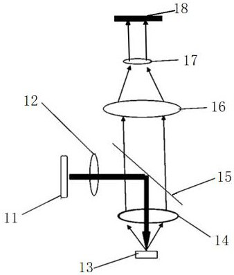
[0042] 1) The beam of the laser light source 11 toward the first compression collimated light path 12, the light passes after compression reflected by the dichroic mirror 15, the beam splitter is provided with two reflection surfaces of the optical film to the bottom of the dichroic mirror 15, the reflected laser light from the main effect of the light source 11;
[0043] 2) the two light rays reflected by the dichroic mirror 15 through the focusing optical paths 1 # 14 shaping diameter 1-3mm focal spot projected on the wavelength conversion device 13, the device is a reflection-type structure, the thermally conductive substrate with a light reflection Lambertian angular distribution to satisfy intensity and said heat conductive substrate using a metal material of good thermal conductivity, is preferably used such as copper, aluminum, or composite materials;
[0044] 3) light 13 reflected by the wavelength conv...
Example
[0046] Second embodiment
[0047] In practice, for the following steps:
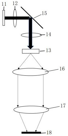
[0048] 1) The beam of the laser light source 11 toward the first compression collimated light path 12, the light passes after compression reflected by the dichroic mirror 15, which is provided with two reflection surfaces of the optical film 15 to the bottom of the dichroic mirror, the optical film is preferably spectroscopic optical film, primarily as a reflected light of the laser light source 11;
[0049] 2) the two light rays reflected by the dichroic mirror 15 through the focusing optical paths 1 # 14 shaping diameter 1-3mm focal spot projected onto the wavelength conversion device 13, the device is a transmission type structure, and the angle of the light transmission intensity after satisfying Lambertian distributed;
[0050] 3) the wavelength conversion device 13 is transmitted rays of light after the wavelength conversion, and then reaches the light shaping optical path 16;
[0051] 4) the light pas...
Example
[0052] Third Example
[0053] In practice, for the following steps:
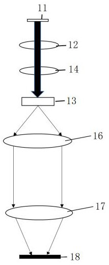
[0054] 1) The beam of the laser light source 11 toward the first compression collimated optical path 12;
[0055] 2) after compression after light focused light path # 1 14 shaping diameter 1-3mm focal spot is projected into the wavelength conversion device 13, the device is a transmission type structure, the intensity and angle of light transmittance satisfying the Lambertian distribution;
[0056] 3) the wavelength conversion device 13 is transmitted rays of light after the wavelength conversion, and then reaches the light shaping optical path 16;
[0057] 4) the light passing through the light path 16 and then shaping shaping the focused light is transmitted through the path # 2 out of 17, to give the desired light, and then projected onto the DMD chip 18.
[0058] In summary, the present embodiment is simple in structure, easy to operate, using the single solid-state laser light source module, the optical pa...
PUM
 Abstract
Description
Claims
Application Information
 - R&D Engineer
- R&D Manager
- IP Professional
- Industry Leading Data Capabilities
- Powerful AI technology
- Patent DNA Extraction
Browse by: Latest US Patents, China's latest patents, Technical Efficacy Thesaurus, Application Domain, Technology Topic.
© 2024 PatSnap. All rights reserved.Legal|Privacy policy|Modern Slavery Act Transparency Statement|Sitemap