Fourth shaft provided with strong braking system for machining of numerical control machine tool
A braking system and CNC machine tool technology, applied in the field of the fourth axis, can solve the problems of low braking efficiency and high motor temperature, and achieve the effects of improving processing efficiency, efficient heat dissipation, and improving braking efficiency
- Summary
- Abstract
- Description
- Claims
- Application Information
AI Technical Summary
Problems solved by technology
Method used
Image

Examples
Example Embodiment
[0037] Example 1
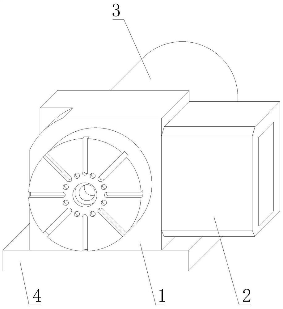
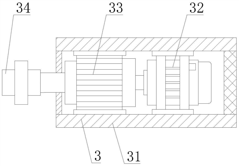
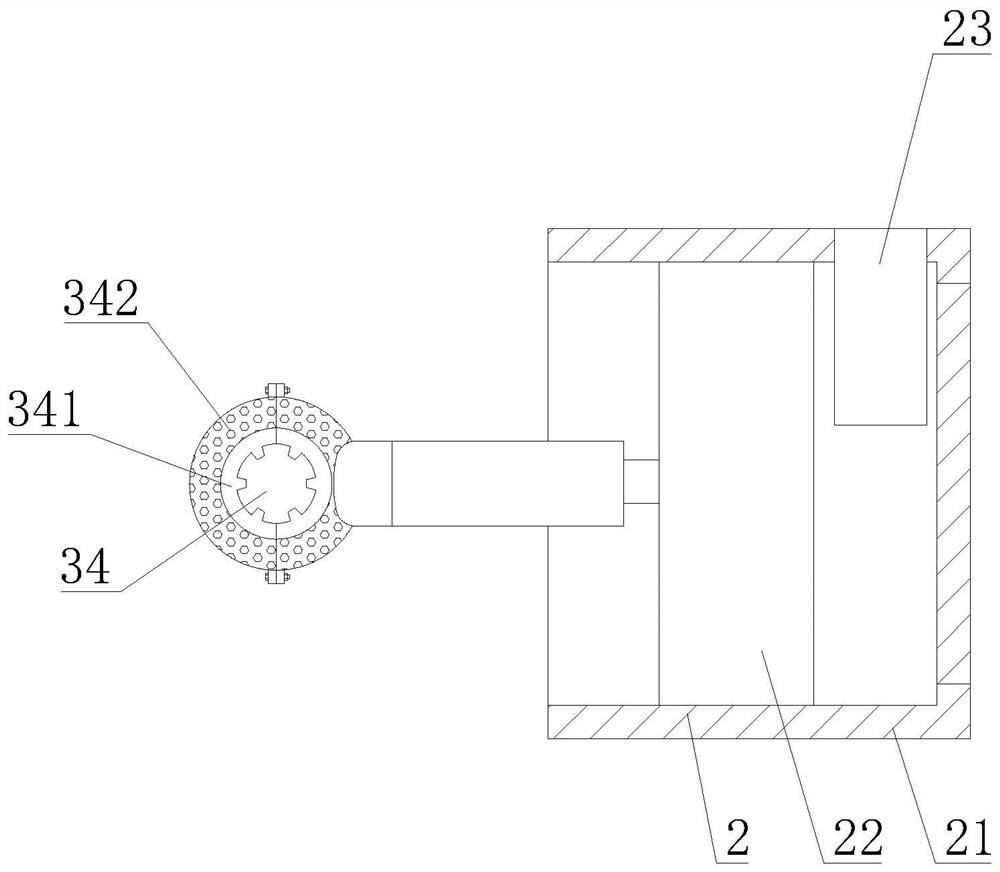
[0038] like Figure 1-9As shown, the present invention provides a fourth shaft for CNC machine tool processing with a strong braking system, comprising a fourth shaft body 1, a workpiece fixing chuck is fixedly installed on the front of the fourth shaft body 1, and the workpiece fixing chuck is The front is provided with a fixing groove, the right side of the fourth axis body 1 is provided with a strong braking mechanism 2, the back of the fourth axis body 1 is provided with a motor cooling mechanism 3, and the bottom of the fourth axis body 1 is provided with an installation mechanism 4, strong braking The mechanism 2 includes an alloy casing 21, which is detachably connected to the right side of the fourth shaft body 1, and a brake driving mechanism 22 is arranged in the inner cavity of the alloy casing 21. The brake driving mechanism 22 includes a driving motor 221, which drives The motor 221 is fixedly installed on the front of the inner cavity of the a...
Example Embodiment
[0039] Example 2
[0040] like Figure 1-9 As shown, on the basis of Embodiment 1, the present invention provides a technical solution: preferably, the output shaft of the drive motor 221 is fixedly connected with an active rod 222, and the back of the active rod 222 rotates with the back of the inner cavity of the alloy shell 21 The front side of the inner cavity of the alloy shell 21 is rotatably connected with the driven rotating rod, the reverse gear 224 is fixedly installed on the back of the driven rotating rod, the driving gear 223 is fixedly installed on the outer wall of the driving rod 222, and the reverse gear 224 The right side meshes with the left side of the driving gear 223. The front and back of the inner cavity of the alloy housing 21 are respectively fixed with a screw rod 1 225 and a screw rod two 226. There is a chain transmission mechanism body 227, one end of the chain transmission mechanism body 227 located at the bottom away from the second screw rod 2...
Example Embodiment
[0041] Example 3
[0042] like Figure 1-9 As shown, on the basis of Embodiment 1, the present invention provides a technical solution: preferably, a sliding seat 228 is slidably connected to the outer walls of the first screw rod 225 and the second screw rod 226, and the left side of the sliding seat 228 extends to In the inner cavity of the fourth shaft body 1, the left side of the sliding seat 228 is detachably connected with the clamping moving plate 229, the left side of the clamping moving plate 229 is detachably connected with the wear plate 2291, and the front and The air blower 2292 is fixedly installed on the back, the air collecting cover 232 is fixedly connected to the bottom of the fan 231, the front of the air collecting cover 232 is provided with an air outlet, and the bottom of the air collecting cover 232 is fixedly connected with a cooling square tube 233, a brake cooling tube 23 A hot air discharge plate 234 is fixedly connected to the outer wall of the 234...
PUM
 Abstract
Description
Claims
Application Information
 - R&D Engineer
- R&D Manager
- IP Professional
- Industry Leading Data Capabilities
- Powerful AI technology
- Patent DNA Extraction
Browse by: Latest US Patents, China's latest patents, Technical Efficacy Thesaurus, Application Domain, Technology Topic.
© 2024 PatSnap. All rights reserved.Legal|Privacy policy|Modern Slavery Act Transparency Statement|Sitemap