Blank for tube plate forming, manufacturing method of blank and tube plate in-vitro forging method
A manufacturing method and blank technology, which can be used in manufacturing tools, forging/pressing/hammer devices, forging/pressing/hammering machines, etc., and can solve the problem of inability to integrally form super-large tube sheets.
- Summary
- Abstract
- Description
- Claims
- Application Information
AI Technical Summary
Problems solved by technology
Method used
Image

Examples
Embodiment 1
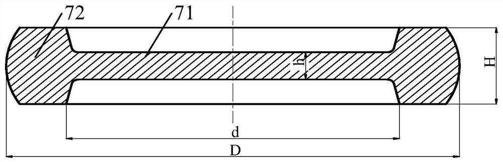
[0067] This embodiment provides a tube sheet forming blank, see Figure 1 to Figure 2 , including the internal forging area 71 and the external forging area 72 located at the edge of the internal forging area 71, the thickness of the internal forging area 71 is smaller than the thickness of the external forging area 72, the thickness h of the internal forging area 71 is the final dimension of the tube sheet forming, and the blank along the The cross-sectional shape in the axial direction is I-shaped, that is, the shape of the above-mentioned blank is thin in the middle and thick in the periphery.
[0068] During implementation, the internal forging area 71 of the blank is completed in the forging equipment (for example, free forging hydraulic press, crank press, screw press, friction press or forging hammer), and the in vitro forging area 72 of the blank is completed outside the forging equipment , in the in vitro forging process of the blank, since the internal forging area 7...
Embodiment 2
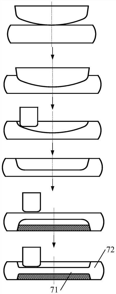
[0082] This embodiment provides a method for making a blank for tube sheet forming, see image 3 , for making the tube sheet forming blank provided by Embodiment 1, the above-mentioned manufacturing method includes the following steps:
[0083] Step 1: Upsetting and unloading the steel ingot to obtain the original billet;
[0084] Step 2: In the forging equipment, thicken and widen the original billet to obtain the billet to be processed;
[0085] Step 3: Forging the central area of the billet to be processed to form an internal forging area 71, and the undivided and finished part is an external forging area 72, so as to obtain a tube plate forming billet.
[0086] Compared with the prior art, the beneficial effects of the manufacturing method of the tube sheet forming blank provided in this embodiment are basically the same as those of the tube sheet forming blank provided in Embodiment 1, and will not be repeated here.
[0087] Specifically, in the above preparation meth...
Embodiment 3
[0091] This embodiment provides an in vitro forging method for a tube sheet, comprising the following steps:
[0092] Make the blank of tube sheet forming, the preparation method of blank is the preparation method of the tube sheet forming blank that embodiment two provides;
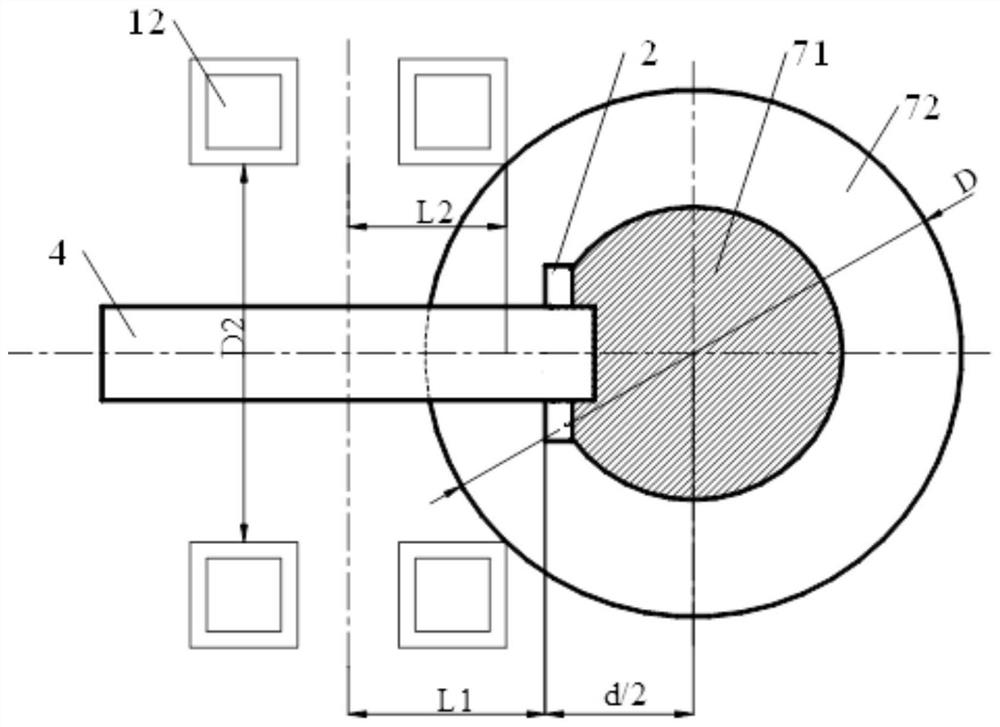
[0093] Outside the forging equipment, the external forging area 72 of the blank 7 is forged by using the hammer 2 of the tooling auxiliary tool to obtain a tube plate.
[0094] Compared with the prior art, the beneficial effects of the in vitro forging method for the tube sheet provided in this embodiment are basically the same as those of the tube sheet formed blank provided in Embodiment 1, and will not be repeated here.
[0095] Specifically, the above-mentioned tooling accessories, see Figure 4 to Figure 5, including beam body 1, hammer head 2 and forging platform 3, define one end of beam body 1 as the forging side, and the other end of beam body 1 as the non-forging side, that is to say, hammer h...
PUM
 Abstract
Description
Claims
Application Information
 - Generate Ideas
- Intellectual Property
- Life Sciences
- Materials
- Tech Scout
- Unparalleled Data Quality
- Higher Quality Content
- 60% Fewer Hallucinations
Browse by: Latest US Patents, China's latest patents, Technical Efficacy Thesaurus, Application Domain, Technology Topic, Popular Technical Reports.
© 2025 PatSnap. All rights reserved.Legal|Privacy policy|Modern Slavery Act Transparency Statement|Sitemap|About US| Contact US: help@patsnap.com