[0020] In order to facilitate understanding of the present invention, the present invention will be further described with reference to the related drawings. The preferred embodiment of the present invention is given in the drawings. However, the present invention can be implemented in many different forms, is not limited to the embodiments described herein. Conversely, the purpose of providing these examples is to make the understanding of the disclosure of the present invention more thoroughly.
[0021] It should be noted that when the element is referred to as "fixed to" another element, it can be directly in another element or may exist in the hidden element. When an element is considered to be "connected" another element, it can be directly connected to another element or may exist at the same time. The term "vertical", "horizontal", "horizontal", "left", "right", and similar expressions are merely illustrative, and the only embodiment is not shown.
[0022] All technical and scientific terms used herein are commonly understood by those skilled in the art of the present invention, unless otherwise defined. The terminology used in the specification of the present invention is intended to describe the embodiments of the specific embodiments, and is not intended to limit the invention. The terms "and / or" as used herein include any and all combinations of one or more related items.
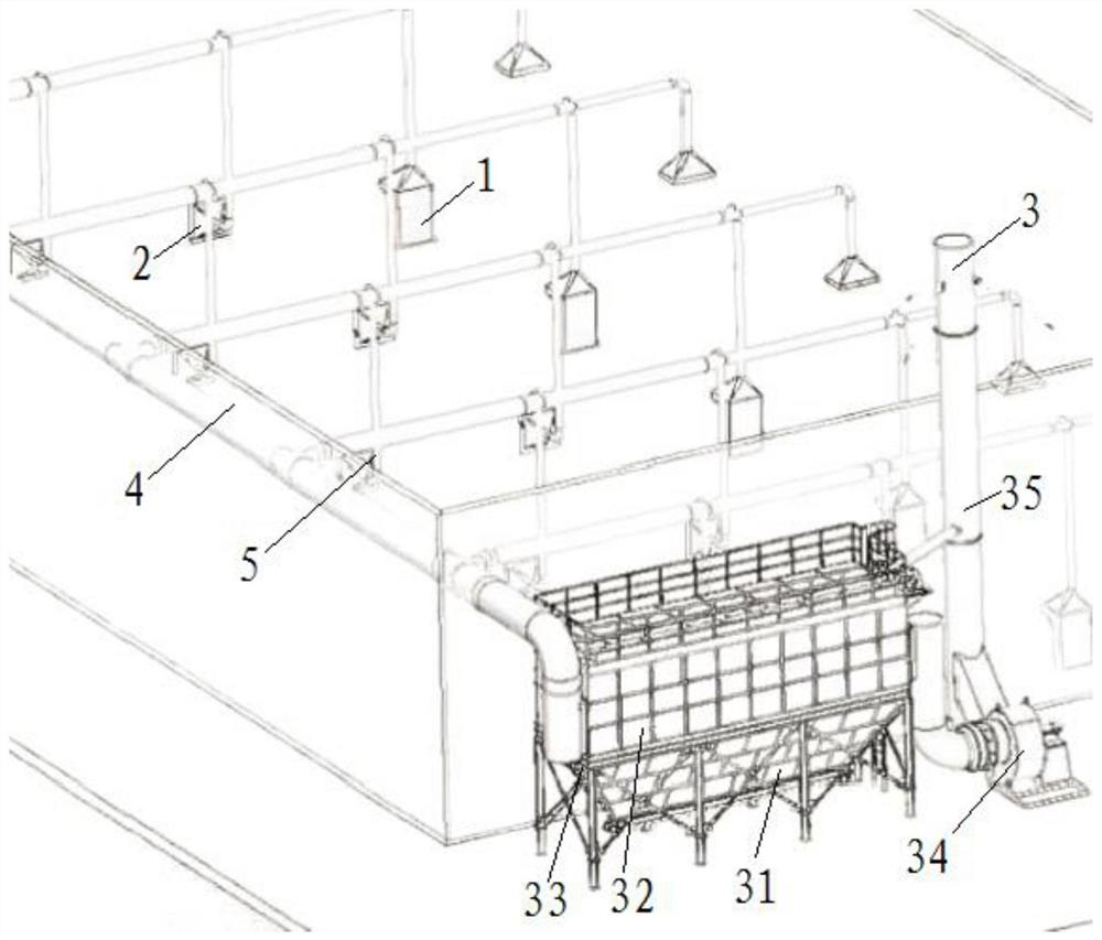
[0023] See Figure 1-5 Shown, an embodiment of the present invention provides a recovery industrial cleaning, comprising: a welding workpiece studio 1, 2 small pieces of the table and the discharge unit 3.
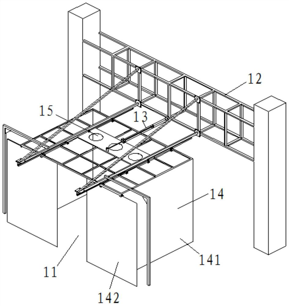
[0024] Welding a workpiece comprises a welding station 1 chamber 11, chamber frame 12, the drive unit 13, the transparent protection unit 14 and the first suction unit 15, the welding station 11 can be placed and welded on a workpiece, said chamber backbone 12 is provided at one side of the welding station 11, the transparent protective unit 14 via the drive unit 13 is connected to the working chamber 12 of the backbone, the drive unit 13 can drive the transparent prevention cover is provided closing means 14 moves the welding station 11 or remote from the welding station 11; the first suction unit 15 is disposed on the transparent protective unit 14, and the first suction unit 15 can be the transparent protective unit 14 after absorption of the smoke delivered to the suction in the main duct 4;
[0025] Small pieces of the table 2 comprises a table body 21 and a second suction unit 22, the second suction unit 22 is disposed on the side surface of the table body 21, the second suction unit body 22 can be absorbed table after dust on the suction conveyor 21 to the main duct 4;
[0026] Discharge unit 34 connected to the suction main duct, the discharge unit 3 can suction the dust in the main duct 4 is discharged.
[0027] Incidentally, the welding chamber 1 in the workpiece, the workpiece may be first lifting the welding station 11, then mobile unit 14 to the transparent protective shield for a welding station 11, a first suction unit 15 is capable of after the soot said transparent prevention unit 14 suction to transport the absorbent main pipe 4, which avoids interference problems lifting the workpiece. Alternatively, the cylinder drive unit 13 is optional 1500 stroke.
[0028] The commercial dust recovery apparatus for welding a workpiece 1 and the small pieces of the stage chamber 2, a first suction unit 15 through the second suction unit 22 and the dust suction intake main pipe 4, and then, through the discharge unit 3 soot in main duct 4 is discharged after dust filter, which can fully cover the welding workshop since the welding smoke, dust and other harmful gases directly into the air, and verified to meet environmental requirements, improving the working environment of employees, the workshop air quality.
[0029] In an embodiment of the present invention, the transparent protective unit 14 includes a shade 141 and a transparent polyurethane blind body 142, the curtain 141 and the transparent polyurethane blind body 142 enclose a space a vacuum, the movable shade 142 is disposed on the side of the suction space side, and the movable shade 142 may open or close the suction space. Polyurethane transparent curtain 141 can function as flame arresters of smoke, the movable shade 142 is provided in order to facilitate the operator enters the suction space operation, maintenance and the like.
[0030] In this embodiment, the movable blind 142 using the double-door manner, a large area of its opening and closing, adapt to a wide range. Meanwhile, the top movable shade 142 is slid through the chute, which can ensure accuracy of fit blind body 142 and the transparent polyurethane curtain 141 to prevent the generation of the large gap.
[0031] In an embodiment of the present invention, the first suction unit 15 comprises at least one suction opening, said suction outlet is provided on top of the transparent polyurethane curtain 141, the suction outlet 5 via the suction duct fans 4 is connected to the main duct. In this embodiment, the suction opening can be provided at the top of the transparent polyurethane transparent protective curtain unit 141 produces soot 14 is conveyed to the shortest path to the suction main pipe 4, which can improve the dust collection efficiency of the dust, and further, further suction opening position is provided to avoid causing interference to other parts. Alternatively, duct fan 5 is 320W high efficiency and low noise fan duct.
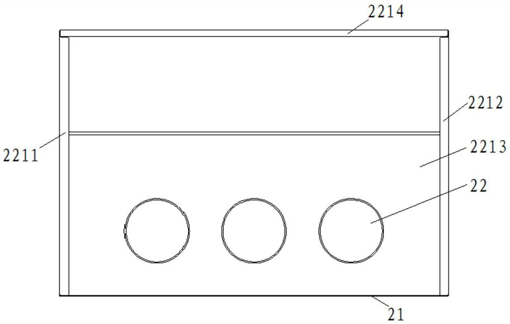
[0032] In an embodiment of the present invention, the second suction unit 22 includes a cover body 221 and the suction duct 222, the cover 221 is fixed on the side surface of the table body 21, the cover member 221 by suction the suction tube 222 is connected to main duct 4, wherein the body 2212214, the left fixing plate 2211 includes a left fixing plate 2211, a right fixing plate 2212, rear plate 2213 and the fixed top cover of the swash plate, fixed to the right plate 2212 are respectively fixed to left and right sides of the top of the swash plate 2214, the rear fixing plate 2213 is fixed to the left fixing plate 2211, rear plate 2212 fixed to the right.
[0033] In an embodiment of the present invention, the discharge unit 3 includes a dust collection box 31, the dust recovery box 31 is provided inside the filter plate 32, the suction recovery tank inlet valve via the reverse blocking and 3331 the main duct 4 is connected to the suction outlet of the suction recovery tank 31 by the centrifugal fan 34 and the exhaust duct 35 is connected to the exhaust duct 35 communicating with the atmosphere.
[0034] Incidentally, the dust collection box 31 inside the filter plate 32 a total of six, are arranged uniformly inside the vacuum partition recovery box 31, the filter plate 32 energy efficiency filter dust, smoke exhaust air filter centrifugal fan 34 can be reduced 32 pairs of exhaust flaps.
[0035] The various technical features of the above examples may perform any combination, in order to make the description, the various technical features of the above embodiments are not described, however, as long as the combination of these technical features does not have contradictions,It should be considered as the scope of this specification.
[0036] The above embodiments are merely illustrative of the embodiments of the present application, but is not understood to limit the limitation of the patent scope of the present application.It should be noted that for those skilled in the art, several deformations and modifications can be made without departing from the context of this application, which belongs to the scope of the present application.Therefore, the scope of protection of the patent according to the present application should be taken in the appended claims.