Check patentability & draft patents in minutes with Patsnap Eureka AI!

Plasma display driving method

A driving method and display panel technology, applied to static indicators, instruments, etc., can solve problems such as deterioration of image quality

Inactive Publication Date: 2004-01-28
HITACHT MAXELL LTD
View PDF1 Cites 0 Cited by
  • Summary
  • Abstract
  • Description
  • Claims
  • Application Information

AI Technical Summary

Problems solved by technology

This erroneous discharge degrades the quality of the displayed image

Method used


Image

  • Plasma display driving method
  • Plasma display driving method
  • Plasma display driving method

Examples


Embodiment Construction

[0052] Preferred embodiments of the present invention will now be explained with reference to the accompanying drawings.

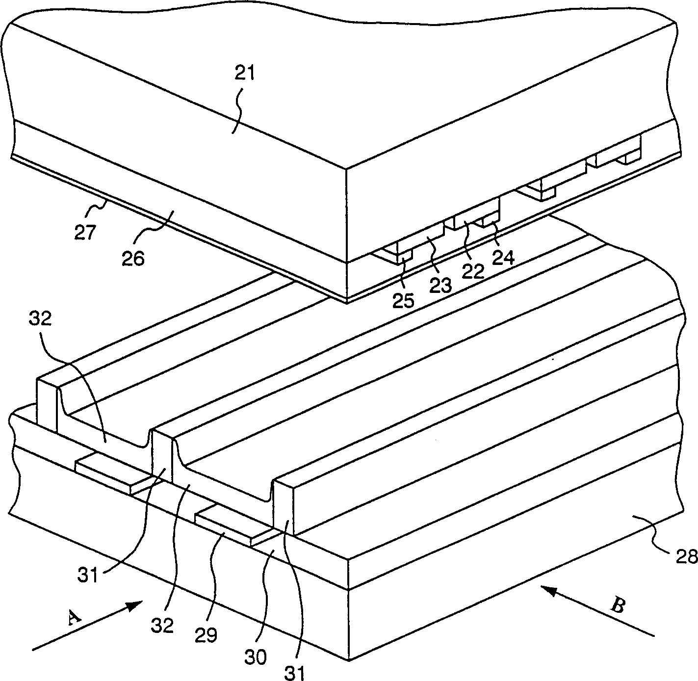
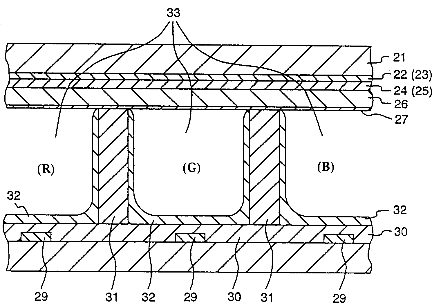
[0053] figure 2 is a schematic diagram illustrating a structural example of a plasma display panel as a first embodiment of the present invention. In this figure, on the lower surface of the front glass substrate 21, a transparent X electrode 22 and a transparent Y electrode 23 are provided in parallel to each other. In addition, these X electrodes 22 and Y electrodes 23 are laminated with X bus electrodes 24 and Y bus electrodes 25 , respectively. Also, a dielectric layer 26 is formed on the other lower surfaces of these bus electrodes, and a dielectric layer 26 including, for example, manganese dioxide MnO is provided on the lower surface thereof. 2 etc. protective layer 27.

[0054] On the other hand, a so-called address A electrode 29 is provided on the upper surface of a rear glass substrate 28 disposed opposite to the front glass substrate, perpen...


PUM


Abstract

The present specification and drawings disclose a technique to display image on the display panel using subfield. Particularly, it is disclosed that the technique for conducting the reset operation by impressing, to the electrode of cells, a plurality of reset pulses per one subfield in the subfield period for the reset operation and then conducting the address operation for selecting cells for display discharge. Further, it is disclosed that the display technique for causing the cells of display panel to conduct display discharge for image display through the reset operation and address operation. Namely, it is the technique for impressing the auxiliary pulse to the electrode of cells after impression of reset pulse for reset operation to form charges in inverse voltage to the scan pulse during the address operation and then conducting the address operation for selecting the cells for display discharge.

Description

technical field [0001] The present invention relates to discharge type display technology, for example, to the display technology of plasma display panels to be introduced, to display devices for personal computers and workstations, or to flat-type wall-mounted television receivers, and furthermore, to advertising and information display devices etc. technology. Background technique [0002] Plasma display devices, for example, realize physically thinner structures in place of physically thick structures such as existing cathode ray tube (CRT) systems, which are especially expected to be large-scale display systems. [0003] For example, in a plasma display device, for each brightness, a field (a display image) is divided into multiple subfields, and ultraviolet rays are generated by the discharge of each pixel (display unit) to activate for the purpose of light emission. Phosphor set. This discharge is called a sustain discharge, and halftones are displayed by changing th...

Claims


Application Information

Patent Timeline
Patent Type & Authority Patents(China)
IPC IPC(8): G09G3/20G09G3/288G09G3/291G09G3/292G09G3/298
CPCG09G2320/0209G09G3/2927G09G3/292
Inventor 曾田健夫佐佐木孝石垣正治大高広
Owner HITACHT MAXELL LTD
Features
  • R&D
  • Intellectual Property
  • Life Sciences
  • Materials
  • Tech Scout
  • Unparalleled Data Quality
  • Higher Quality Content
  • 60% Fewer Hallucinations
Learn More