Supercharge Your Innovation With Domain-Expert AI Agents!

Fixed constant-velocity universal joint

A technology of universal joints and couplings, which is applied in the direction of couplings, elastic couplings, mechanical equipment, etc., can solve the problems of weight increase, outer diameter of outer coupling components, etc., and achieve strength improvement , to ensure the effect of isokinetic

Pending Publication Date: 2021-11-16
NTN CORP
View PDF1 Cites 0 Cited by
  • Summary
  • Abstract
  • Description
  • Claims
  • Application Information

AI Technical Summary

Problems solved by technology

As a proposal to extend the track groove of the outer joint member, there is a proposal to increase the pitch circle diameter (PCD) of the ball, but this leads to an increase in the outer diameter of the outer joint member and an increase in weight.

Method used


Image

  • Fixed constant-velocity universal joint
  • Fixed constant-velocity universal joint
  • Fixed constant-velocity universal joint

Examples


Embodiment Construction

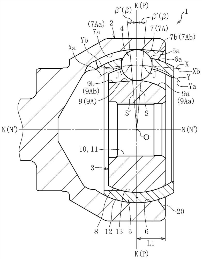
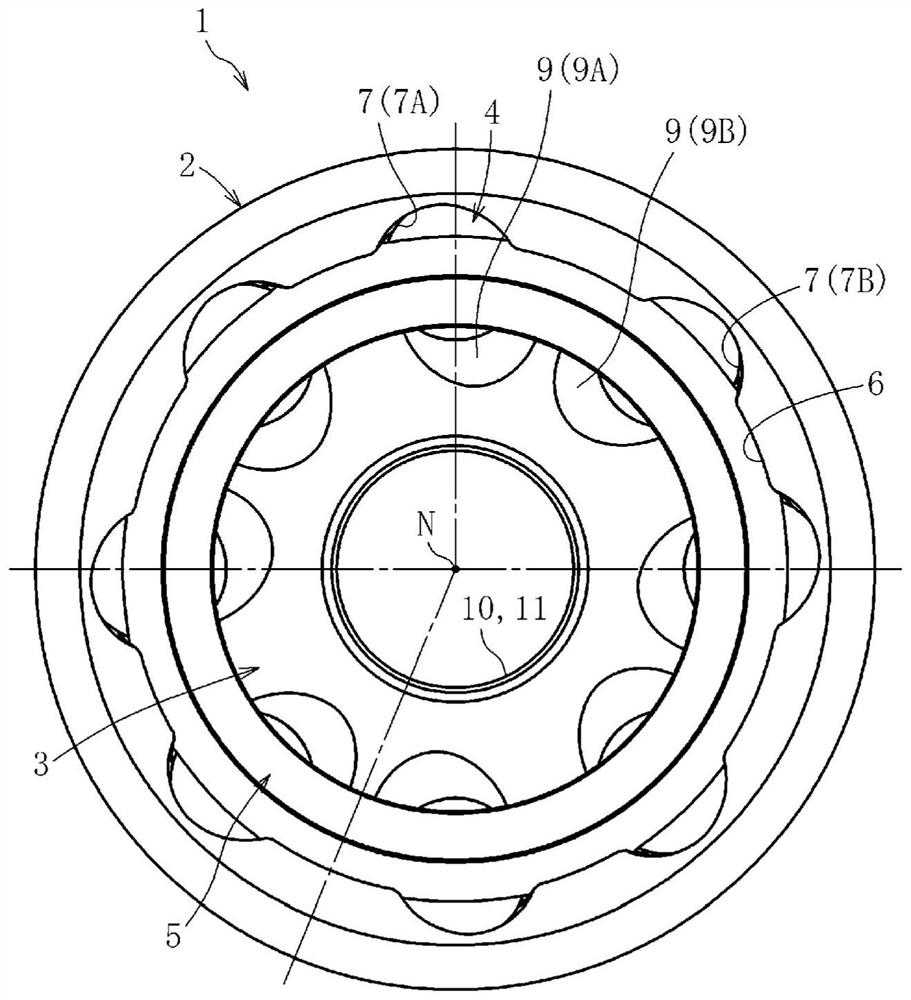
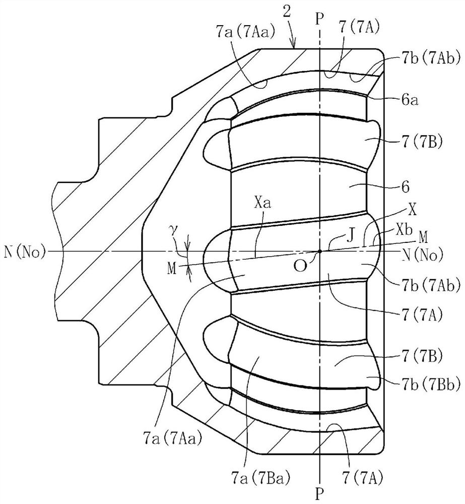
[0056] Based on Figure 1~ Figure 11 A fixed constant velocity universal joint according to one embodiment of the present invention will be described. Figure 1a is a longitudinal sectional view of a fixed constant velocity universal joint according to an embodiment of the present invention, Figure 1b yes Figure 1a right side view of . Figure 2a yes Figure 1a Longitudinal sectional view of the outboard coupling member, Figure 2b yes Figure 2a right side view of . Figure 3a yes Figure 1a Longitudinal sectional view of the inboard coupling member, Figure 3b yes Figure 3a right side view of . Such as Figure 1a , Figure 1b As shown, the fixed constant velocity universal joint 1 of this embodiment is a fixed constant velocity universal joint of the cross raceway groove type, and the outer joint member 2, the inner joint member 3, Torque transmission balls (hereinafter also simply referred to as balls) 4 and cages 5 are the main components. Eight raceway grooves ...


PUM


Abstract

The invention discloses a a fixed constant-velocity universal joint (1) in which a track center line (X) of a track groove (7) of an outer joint member (2) includes at least an arcuate portion having a center of curvature with no axial offset with respect to a joint center (O), a plane (M) including the track center line (X) and the joint center (O) is inclined with respect to a joint axis (N-N) and the inclination direction thereof is formed in mutually opposite directions in the circumferentially adjacent track grooves (7), and a track center line (Y) of a track groove (9) of an inner joint member (3) is formed in mirror image symmetry with the track center line (X) of the track grooves (7) forming a pair in the outer joint member (2) with respect to a plane (P) that includes the joint center (O) and is orthogonal to the joint axis (N-N) in a state with an operating angle of 0 degree, the present invention is characterized in that at least one torque transmission ball (4) that moves to the opening side of the track groove (7) of the outer joint member (2) has an operating form in which the contact point with the opening-side end of the track groove (7) of the outer joint member (2) is lost when a maximum operating angle [theta]max is taken, and in the state with an operating angle of 0 degree, an end of a retainer (5) axially projects from the opening-side end of the outer joint member (2).

Description

technical field [0001] The invention relates to a fixed constant velocity universal joint. Background technique [0002] The constant velocity universal joint that constitutes the power transmission system of automobiles and various industrial machines can connect the two shafts on the driving side and the driven side in a torque-transmittable manner, and even if the two shafts take an operating angle Rotational torque can be transmitted at a constant speed. Constant velocity universal joints are roughly divided into fixed constant velocity universal joints that allow only angular displacement and sliding constant velocity universal joints that allow both angular displacement and axial displacement. In the drive shaft that transmits power from the engine of a motor vehicle to the drive wheels, a sliding constant velocity universal joint is used on the differential side (inner side of the machine), and a fixed constant velocity universal joint is used on the driving wheel si...

Claims


Application Information

Patent Timeline
Patent Type & Authority Applications(China)
IPC IPC(8): F16D3/224
CPCF16D2003/22309F16D3/2245F16D3/224Y10S464/906
Inventor 藤尾辉明船桥雅司
Owner NTN CORP
Features
  • R&D
  • Intellectual Property
  • Life Sciences
  • Materials
  • Tech Scout
  • Unparalleled Data Quality
  • Higher Quality Content
  • 60% Fewer Hallucinations
Learn More