Ultrasonic knife self-adaptive automatic triggering system
An automatic triggering and self-adaptive technology, applied in medical science, surgery, etc., can solve problems such as device volume reduction, achieve miniaturization, reduce the risk of misoperation, and increase flexibility.
- Summary
- Abstract
- Description
- Claims
- Application Information
AI Technical Summary
Problems solved by technology
Method used
Image
Examples
no. 1 approach
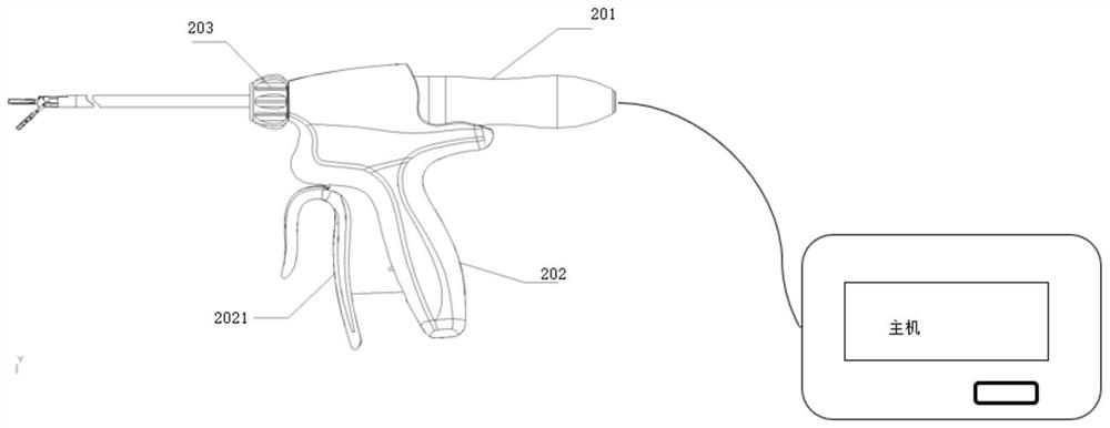
[0028] see Figure 1-3 A first embodiment of the ultrasonic blade control system of the present disclosure is shown, wherein like reference numerals refer to like components.
[0029] The structure of the ultrasonic knife control system is as follows: Figure 1-2 As shown, the ultrasonic scalpel control system includes an ultrasonic scalpel and an ultrasonic host. The ultrasonic scalpel is electrically connected with the ultrasonic main body.
[0030] Specifically as image 3 As shown, the ultrasonic scalpel includes a transducer 201 , a handle assembly 202 , and a cutter head assembly 203 . The cutter head assembly 203 further includes a casing assembly, a horn in the bushing assembly, and an execution assembly, the execution assembly includes a cutter head integrally formed with one end of the horn, and rotates relative to the cutter head jaws. The horn in the cutter head assembly is connected with the transducer 201 .
[0031] The handle assembly 202 includes a trigger...
no. 2 approach
[0040] Figure 4 A second embodiment of the ultrasonic scalpel control system of the present disclosure is shown. This embodiment is a further improvement on the first embodiment.
[0041] In the second embodiment, a handle abutting portion is provided inside the L-shaped long arm of the L-like trigger 2021 body. The trigger switch is arranged on the grip portion 2022 of the handle. Correspondingly, a guide structure is provided on the grip portion 2022 of the handle. Exemplarily, the guide structure is a slide rail, and a trigger switch is disposed on the inner wall of the handle grip portion 2022 . Further, different slots can be provided on the sliding track, and buckles matching the slots can be provided on the abutting portion of the handle.
[0042] when along the Figure 4 When the trigger is pulled in the direction of the middle arrow, the abutting part of the handle can move along the sliding rail toward the trigger switch on the inner wall of the grip part of the...
no. 3 approach
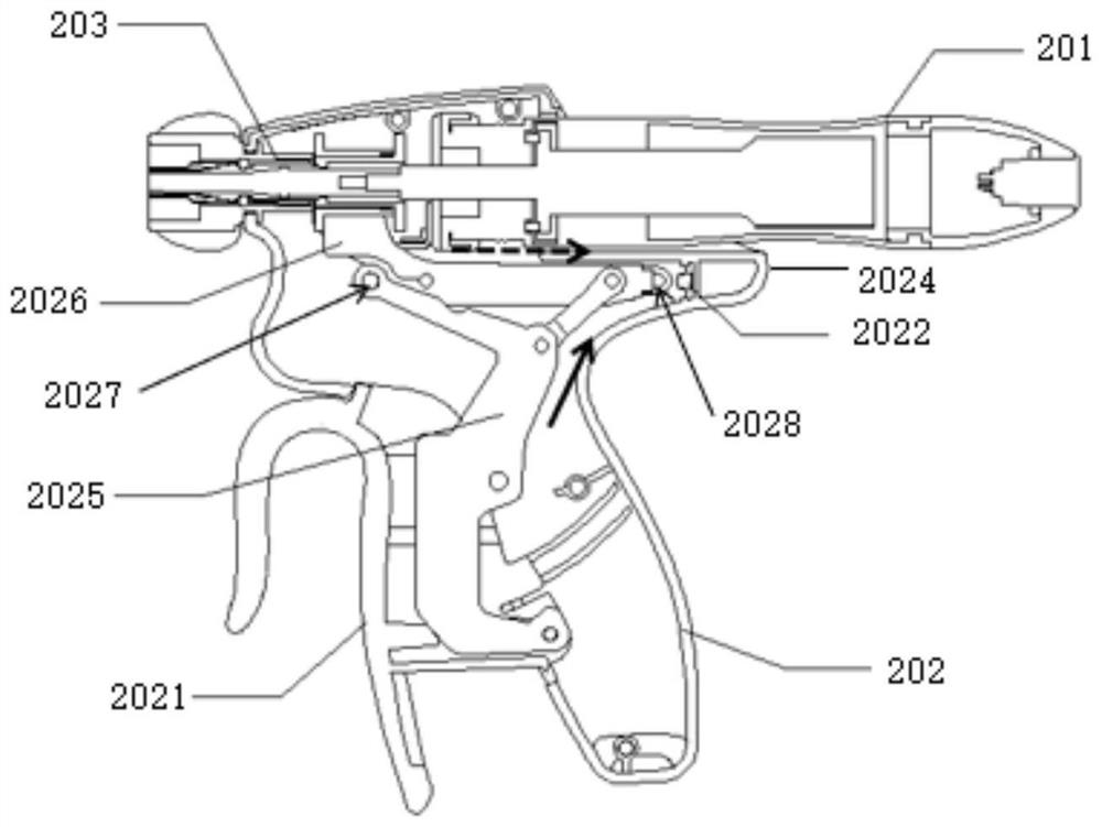
[0045] Figure 5 A third embodiment of the present disclosure is shown. The third embodiment differs from the first embodiment in that, on the basis of the first embodiment, a further improvement is made to the position of the trigger switch.
[0046] The second connecting member is provided with a handle abutment portion towards the distal end of the transducer, and a trigger switch 2022 is provided at a position corresponding to the handle abutment portion on the inner wall of the handle support portion 2024 .
[0047] The abutting portion of the handle of the second connecting member abuts against the trigger switch, and maintains a contact state when the trigger is not pulled, and at this time, excitation of ultrasonic energy cannot be realized.
[0048] When the operator pulls the trigger 2021, the upper part of the trigger rotates around the fixed pin of the trigger, and the L-shaped long arm in the body of the similar L-shaped trigger 2021 starts to move as described i...
PUM
 Abstract
Description
Claims
Application Information
 - R&D Engineer
- R&D Manager
- IP Professional
- Industry Leading Data Capabilities
- Powerful AI technology
- Patent DNA Extraction
Browse by: Latest US Patents, China's latest patents, Technical Efficacy Thesaurus, Application Domain, Technology Topic, Popular Technical Reports.
© 2024 PatSnap. All rights reserved.Legal|Privacy policy|Modern Slavery Act Transparency Statement|Sitemap|About US| Contact US: help@patsnap.com


