Biomass pyrolysis hydrogen production reaction device
A biomass pyrolysis and reaction device technology, which is applied in the field of biomass pyrolysis hydrogen production reaction device, can solve the problems that hinder the development of biomass hydrogen production, low heat transfer efficiency, low hydrogen composition, etc., and achieve sufficient and thorough reaction , Improve reaction efficiency and reduce energy consumption
- Summary
- Abstract
- Description
- Claims
- Application Information
AI Technical Summary
Problems solved by technology
Method used
Image
Examples
Embodiment 1
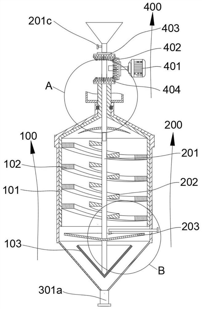
[0027] refer to Figure 1~5 , which is the first embodiment of the present invention, which provides a biomass pyrolysis hydrogen production reaction device, including a gas guide assembly 100 and a bearing assembly 200, the gas guide assembly 100 includes a holding tank 101, a first screw The plate 102 and the deflector 103, the inner wall of the storage tank 101 is provided with a first spiral plate 102, the inner wall of the storage tank 101 is fixedly connected to the first spiral plate 102, the first spiral plate 102 is provided with a deflector 103, the deflector 103 is located Below the first spiral plate 102; the carrying assembly 200 includes a rotating shaft 201, a second spiral plate 202 and a tray 203, the rotating shaft 201 is arranged in the holding tank 101, the end of the rotating shaft 201 is provided with a shroud 103, and the end of the rotating shaft 201 is fixedly connected to the guide. Flow cover 103, the second spiral plate 202 and tray 203 are arranged...
Embodiment 2
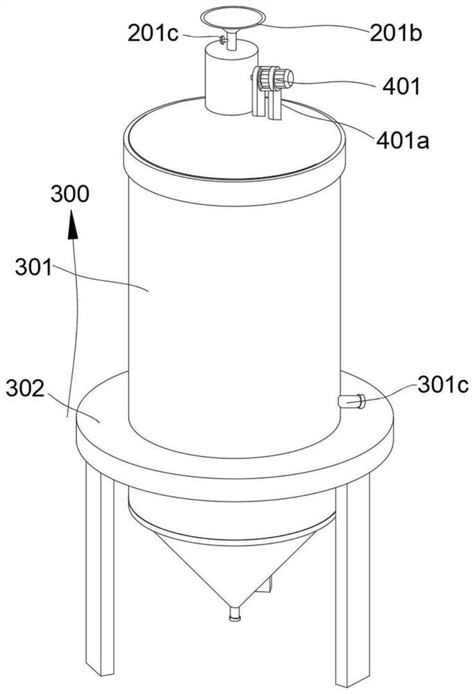
[0030] refer to figure 1 and 3 ~5, is the second embodiment of the present invention. This embodiment is based on the previous embodiment, and also includes a support assembly 300. The support assembly 300 includes an outer tank body 301 and a support base 302. The inner wall of the outer tank body 301 is relatively attached to the container 101 outer wall, the containing tank 101 can rotate 1 on the inner wall of the outer tank body 301, the containing tank 101 communicates with the inside of the outer tank body 301 through an opening 104 provided on the top, and high-temperature smoke can enter the outer tank body 301 through the opening 104, and the outer wall of the outer tank body 301 The support seat 302 is connected, and the outer tank body 301 can be fixed and supported by the support seat 302 .
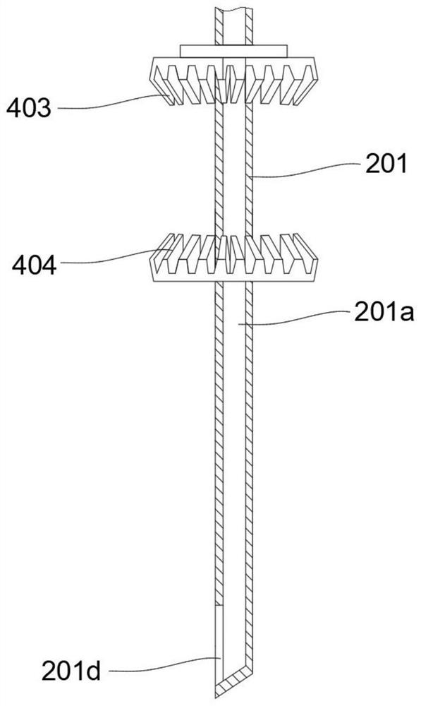
[0031] Specifically, the rotating shaft 201 is provided with an inner chamber 201a, and one end of the inner chamber 201a is provided with a hopper 201b through which cataly...
Embodiment 3
[0040] refer to figure 1 , 4 And 5, for the third embodiment of the present invention, this embodiment is based on the above embodiment, the motor 401 drives the first bevel gear 402 to rotate through the motor shaft, and the first bevel gear 402 drives the second bevel gear 403 and the third bevel When the gear 404 rotates, the second bevel gear 403 and the third bevel gear 404 rotate in opposite directions. When the second bevel gear 403 rotates, it can drive the rotating shaft 201 and the second spiral plate 202 to rotate. A spiral plate 102 rotates, and the first spiral plate 102 and the second spiral plate 202 rotate in opposite directions.
[0041] The high-temperature flue gas enters the outer tank body 301 through the intake pipe 301a, the high-temperature flue gas moves to the first spiral plate 102 along the outer wall of the flow guide 103, guides the high-temperature flue gas to flow upward along the first spiral plate 102, and flows into the storage tank 101 The...
PUM
 Abstract
Description
Claims
Application Information
 - R&D Engineer
- R&D Manager
- IP Professional
- Industry Leading Data Capabilities
- Powerful AI technology
- Patent DNA Extraction
Browse by: Latest US Patents, China's latest patents, Technical Efficacy Thesaurus, Application Domain, Technology Topic, Popular Technical Reports.
© 2024 PatSnap. All rights reserved.Legal|Privacy policy|Modern Slavery Act Transparency Statement|Sitemap|About US| Contact US: help@patsnap.com


