Bolt disassembling and assembling tool
A technology of bolt disassembly and tooling, which is applied in the direction of manufacturing tools, metal processing, metal processing equipment, etc., and can solve problems such as the inability to assemble bolts
- Summary
- Abstract
- Description
- Claims
- Application Information
AI Technical Summary
Problems solved by technology
Method used
Image

Examples
Embodiment 1
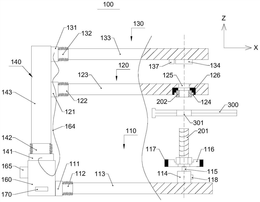
[0057] Please refer to figure 1 , Figure 11 to Figure 12 , Figure 14 to Figure 18 , Embodiment 1 of the present invention provides a bolt removal tool 100, which may include:
[0058] The bolt rotation mechanism 110 includes a first hydraulic pedestal 111, a first telescopic joint 112 arranged on the first hydraulic pedestal 111 to expand and contract in the X direction, and a transmission rod 113 arranged on the first telescopic joint 112 in the X direction , the transmission rod 113 is provided with a bolt sleeve 116, the side and / or bottom of the bolt sleeve 116 is provided with a sleeve magnet 117, the transmission rod 113 is provided with a motor 114, and the motor 114 passes through The motor shaft 115 is connected to the bolt sleeve 116 , the motor 114 drives the bolt sleeve 116 to rotate through the motor shaft 115 , and the motor 114 is provided with a torque sensor 118 . The motor 114 can be a variable frequency motor, so as to rotate at a lower speed when initi...
Embodiment 2
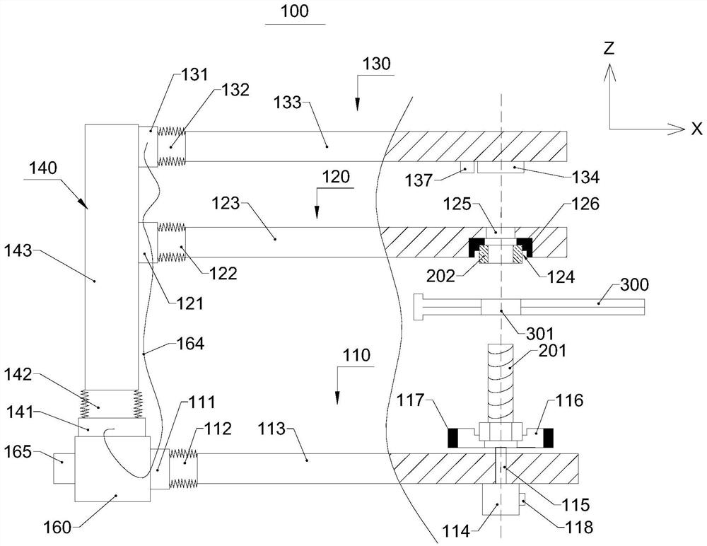
[0079] Please refer to figure 2 , Figure 11 to Figure 12 , Figure 14 to Figure 18 Embodiment 2 of the present invention provides a bolt removal tool 100, which is improved on the basis of Embodiment 1. The difference is that the motor 114 is arranged on the lower surface of the transmission rod 113, and the motor shaft 115 passes through the transmission rod. 113, the bolt sleeve 116 is still located above the transmission rod 113. The advantage is that the height of the bolt sleeve 116 is reduced, and the stability of the bolt sleeve 116 when rotating is improved.
Embodiment 3
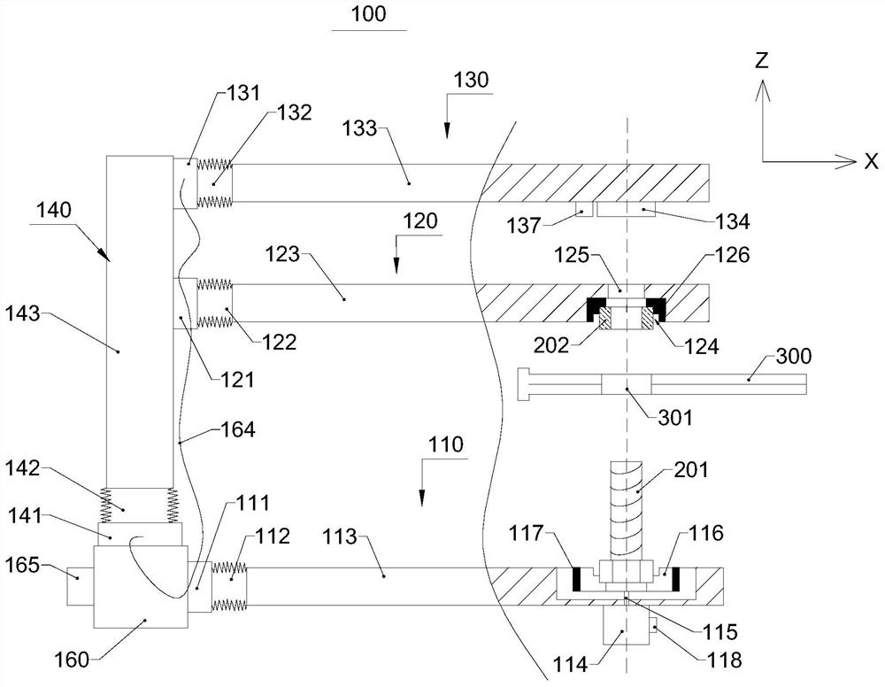
[0081] Please refer to image 3 , Figure 11 to Figure 12 , Figure 14 to Figure 18 Embodiment 3 of the present invention provides a bolt removal tool 100, which is improved on the basis of Embodiment 2. The difference is that the transmission rod 113 is provided with a groove 1131, and the bolt sleeve 116 set in the groove 1131 . The bolt sleeve 116 is arranged in the groove 1131, and when detachment occurs, the bolt sleeve 116 is limited in the groove 1131, which can prevent the safety hazard caused by the detachment and flying out of the bolt sleeve 116 when rotating.
[0082] Please refer to Figure 13 , the sleeve magnet 117 can be arranged on the transmission rod 113 and directly below the bolt sleeve 116, and its magnetic strength is relatively weak compared to the sleeve magnet 117 being arranged on the side and / or bottom of the bolt sleeve 116, Poor adsorption capacity. In order to avoid electromagnetic interference, a rubber pad 119 is provided between the motor...
PUM
 Abstract
Description
Claims
Application Information
 - R&D
- Intellectual Property
- Life Sciences
- Materials
- Tech Scout
- Unparalleled Data Quality
- Higher Quality Content
- 60% Fewer Hallucinations
Browse by: Latest US Patents, China's latest patents, Technical Efficacy Thesaurus, Application Domain, Technology Topic, Popular Technical Reports.
© 2025 PatSnap. All rights reserved.Legal|Privacy policy|Modern Slavery Act Transparency Statement|Sitemap|About US| Contact US: help@patsnap.com