Unlock instant, AI-driven research and patent intelligence for your innovation.

A conveniently installed robot grabbing device

A grasping device and robot technology, applied in the directions of manipulators, manufacturing tools, chucks, etc., can solve the problems of cumbersome disassembly and assembly process of anti-skid parts, easy to be interfered by manipulators, and small clamping space, etc., so as to improve disassembly and assembly efficiency and reduce disassembly and assembly. Easy to install, easy to locate quickly

Active Publication Date: 2022-02-15
SUZHOU DITIAN ROBOT & AUTOMATION CO LTD
View PDF17 Cites 0 Cited by
  • Summary
  • Abstract
  • Description
  • Claims
  • Application Information

AI Technical Summary

Problems solved by technology

[0006] Aiming at the problems existing in the prior art, the object of the present invention is to provide a conveniently installed robot grabbing device, which can effectively solve the problem that the anti-skid rubber pads in the background technology are usually locked by fasteners during installation. This makes it difficult to disassemble and assemble during subsequent replacement, and the jaw space between the manipulators is small, and it is easy to be interfered by the manipulator when using tools for disassembly and assembly. , in this technical solution: before the anti-slip pad is assembled, the positioning shell used to install the anti-slip pad can be moved out of the positioning groove of the grabbing jaw until the positioning shell is away from the jaw mouth area between the grabbing jaws, so that It can expand the operable space for dismounting and assembling the anti-slip pad, and reduce the interference of the grabbing jaws during the disassembly process. After the positioning shell moves out of the jaw mouth area, the positioning shell rotates at the rotating hole of the sliding block through the rotating shaft. Flexibly adjust the angle of the positioning shell to facilitate the disassembly and assembly of the subsequent anti-slip pads. When assembling the anti-slip pads, the anti-slip pads slide into the interior of the positioning shell along the assembly protrusions through the second assembly chute of the anti-slip pad support. The assembly of the anti-slip pad and the grabbing jaw can be completed. Similarly, the anti-slip pad and the grabbing jaw can also be quickly disassembled. The flexible disassembly method simplifies the cumbersome procedure of disassembling and assembling the traditional anti-slip pad. It reduces the difficulty of disassembly and assembly, which is conducive to improving the efficiency of disassembly and assembly. After the anti-skid pad and the positioning shell are assembled, the positioning shell slides into the positioning slot of the grasping jaw through the positioning slide bar, and the positioning groove of the grasping jaw The inner wall of the groove clamps and fixes the positioning shell, which can complete the installation of the anti-slip pad and the grabbing jaw. During the disassembly process, the positioning shell moves on the grabbing jaw by moving out the slider and the slide rail, and is not completely disassembled. The way of positioning the shell and grabbing jaws is convenient for quick positioning during assembly

Method used


Image

  • A conveniently installed robot grabbing device
  • A conveniently installed robot grabbing device
  • A conveniently installed robot grabbing device

Examples


Embodiment 1

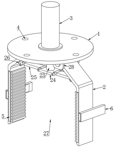
[0036] like figure 1 with figure 2 As shown, a conveniently installed robot grabbing device includes a mounting base 1, a telescopic hydraulic cylinder 3 is provided at the center of the upper surface of the mounting base 1, and one end of the telescopic hydraulic cylinder 3 is provided with a hydraulic cylinder output end 23 One end of the output end 23 of the hydraulic cylinder is fixedly equipped with a movable seat 24, the surface of the movable seat 24 is provided with a jaw connecting plate 25, and one end of the jaw connecting plate 25 is provided with a first rotating seat 26, so A second rotating seat 28 is provided below the mounting seat 1, and the second rotating seat 28 of the mounting seat 1 is provided with a grasping jaw 2, and the outer surface of the grasping jaw 2 is provided with a removal mechanism 6, The inside surface of the grasping jaw 2 is provided with a positioning mechanism 5, and the upper surface of the mounting seat 1 is provided with a mounti...

Embodiment 2

[0038] like image 3 , Image 6 with Figure 7 As shown, the components that are the same as or corresponding to those in Embodiment 1 use the corresponding reference numerals as in Embodiment 1. For the sake of simplicity, only the differences from Embodiment 1 will be described below. The difference between this embodiment 2 and embodiment 1 is that: a conveniently installed removal mechanism of the robot grabbing device includes a removal slide rail 12, and a removal slide block 13 is movably installed inside the removal slide rail 12, so A turning hole 18 is provided on the surface of the removing slider 13, a positioning groove 8 is provided on the grabbing jaw 2, a positioning slot 9 is provided on the grabbing jaw 2, and a positioning groove 9 is provided on the grabbing jaw 2, and the moving out slide rail 12 There is a removal slideway 14 inside, the removal slide block 13 is slidingly connected with the removal slideway 14 of the removal slide rail 12, the removal ...

Embodiment 3

[0040] like Figure 3 to Figure 9 As shown, the components that are the same as or corresponding to those in Embodiment 1 use the corresponding reference numerals as in Embodiment 1. For the sake of simplicity, only the differences from Embodiment 1 will be described below. The difference between this embodiment 3 and embodiment 1 is: a positioning shell, an anti-slip pad support and an anti-slip cushion block of a conveniently installed robot grabbing device, the positioning shell 11 is provided with a first assembly chute 16. The positioning shell 11 is fixedly equipped with assembly protrusions 17, the anti-slip pad support 19 is provided with a second assembly chute 22, and the anti-slip pad 20 is provided with anti-slip lines 21, and the anti-slip lines 21 is evenly distributed on the surface of the anti-skid pad 20, the anti-skid pad support 19 matches the first assembly chute 16 of the positioning shell 11, and the anti-slip pad support 19 is connected to the positionin...


PUM


Abstract

The invention discloses a conveniently installed robot grasping device, which belongs to the technical field of mechanical equipment, and comprises a mounting seat, a second rotating seat is arranged under the mounting seat, and a grasping device is arranged at the second rotating seat of the mounting seat. Take the jaw, the outer surface of the grasping jaw is provided with a removal mechanism, and the inner surface of the grasping jaw is provided with a positioning mechanism. A conveniently installed robot grabbing device according to the present invention can expand the operable space for disassembling and assembling the anti-slip pad, and reduce the interference of the grabbing jaws during the disassembling process. After the positioning shell is moved out of the jaw opening area, The positioning shell can flexibly adjust the angle of the positioning shell through the rotation of the rotating shaft at the rotating hole of the sliding block, which provides convenience for the disassembly and assembly of the subsequent anti-slip pads. In addition, the flexible disassembly method simplifies the cumbersome disassembly and assembly of the traditional anti-slip pads The program reduces the difficulty of disassembly and assembly, and is conducive to improving the efficiency of disassembly and assembly.

Description

technical field [0001] The invention relates to the technical field of mechanical equipment, in particular to a conveniently installed robot grabbing device. Background technique [0002] A robot is an intelligent machine that can work semi-autonomously or fully autonomously, and some robots are equipped with manipulators to perform grasping tasks. [0003] Chinese application number 201310503297.9 describes a simple anti-slip manipulator, including a manipulator bracket, a hydraulic cylinder, a connecting rod and an arm. The hydraulic cylinder is set in the manipulator bracket, and the front end of the manipulator bracket is equipped with an arm. The hydraulic cylinder and the arm are connected by a connecting rod. , the arm is divided into a left arm and a right arm, and the front end of the left arm and the right arm is a hand end, and the hand end is connected to the arm and the end of the manipulator bracket through a pin shaft, and a reset is provided between the left ...

Claims


Application Information

Patent Timeline
Patent Type & Authority Patents(China)
IPC IPC(8): B25J15/08B25J15/00
CPCB25J15/08B25J15/00
Inventor 万信飞赵德强支海波陆郭春黄仕茌
Owner SUZHOU DITIAN ROBOT & AUTOMATION CO LTD