Supercharge Your Innovation With Domain-Expert AI Agents!

Alternating tangential flow pumping method

A technology of tangential flow and air flow, applied in the direction of separation methods, components of pumping devices for elastic fluids, chemical instruments and methods, capable of solving the inability to precisely adjust the duration or flow of positive and negative air flow transitions Quantity, difficult maintenance and other issues

Pending Publication Date: 2021-12-10
瑞普利金公司
View PDF6 Cites 0 Cited by
  • Summary
  • Abstract
  • Description
  • Claims
  • Application Information

AI Technical Summary

Problems solved by technology

Current systems do not precisely adjust the duration of the transition between positive and negative airflow or the amount of airflow
Additionally, current systems often involve many parts in complex assemblies, which are difficult to maintain

Method used


Image

  • Alternating tangential flow pumping method
  • Alternating tangential flow pumping method
  • Alternating tangential flow pumping method

Examples


Embodiment Construction

[0010] review

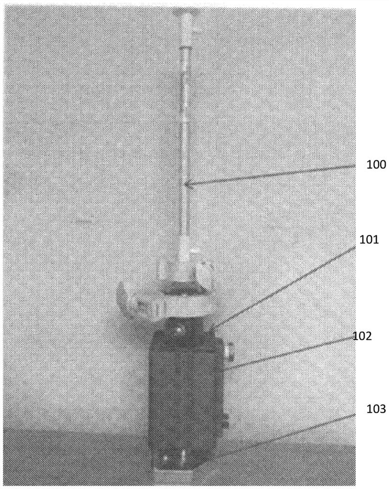
[0011] The present application discloses an alternate tangential flow (ATF) pumping method in which positive and negative pressures are generated in use. This method uses a pneumatic cylinder connected to the diaphragm pump of the ATF filter. The pneumatic cylinder contains a piston that allows the controlled generation of positive and negative pressures on the diaphragm. Movement of the diaphragm allows fluid to enter and exit through the ATF filter. figure 1 Embodiments of the present disclosure are shown. Such as figure 1 As shown, filter 100 is connected to cylinder 102 by base locking feature 101 . The cylinder 102 is also connected to a linear servo via a connection 103 .

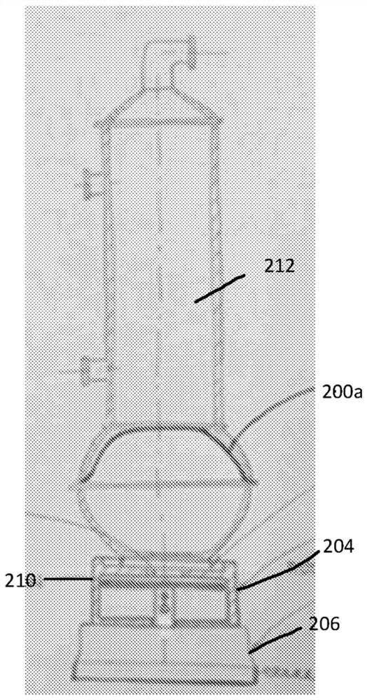
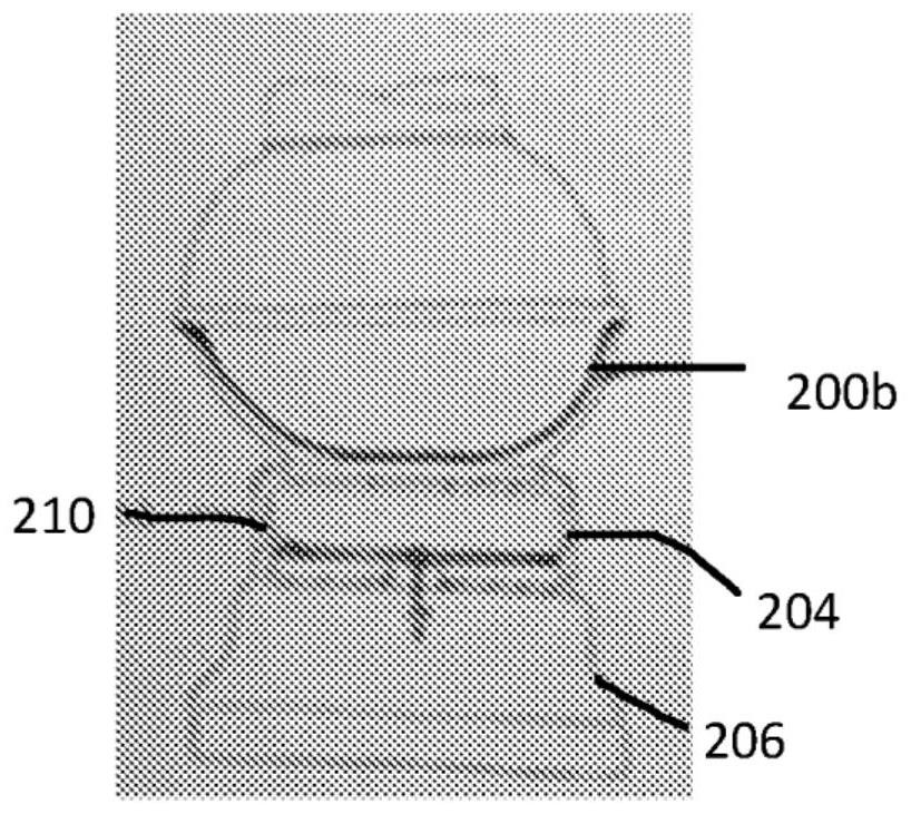
[0012] The end of the cylinder without the piston connecting rod has an opening in the center which leads into the functional chamber of the cylinder. The bottom of the filter dome base has an opening that matches the opening in the end of the cylinder. The cylinder face has a l...


PUM


Abstract

The present disclosure relates generally to alternating tangential flow (ATF) perfusion pumping methods, including novel methods for generating positive and negative pressure at the point of use, and more particularly, to apparatuses, systems and methods for use of the same.

Description

[0001] priority [0002] This application claims priority under 35 U.S.C. §119 to U.S. Provisional Patent Application No. 62 / 850,718, filed May 21, 2019, which is hereby incorporated by reference in its entirety. technical field [0003] The present application relates generally to alternate tangential flow (ATF) perfusion pumping methods, and more particularly to devices, systems, and methods of using the same. Background technique [0004] Filtration is generally performed to separate, clarify, modify and / or concentrate fluid solutions, mixtures or suspensions. In the biotechnology and pharmaceutical industries, filtration is critical to the successful production, processing and testing of new drugs, diagnostics and other biological products. For example, in the process of manufacturing biological products, animal cell cultures are used, filtration is performed to clarify, selectively remove and concentrate certain components from the culture medium, or to modify the cult...

Claims


Application Information

Patent Timeline
IPC IPC(8): F04B43/02B01D29/88B01D29/90B01D35/26F04B43/00F04B43/04
CPCB01D29/90B01D35/26F04B43/067F04B53/20F04B49/065F04B2203/0903F04B2203/04F04B2201/12F04B2201/0209F04B2205/09F04B43/04B01D2313/243F04B43/0081
Inventor 鲁道夫·帕弗里克
Owner 瑞普利金公司
Features
  • R&D
  • Intellectual Property
  • Life Sciences
  • Materials
  • Tech Scout
  • Unparalleled Data Quality
  • Higher Quality Content
  • 60% Fewer Hallucinations
Learn More