Supercharge Your Innovation With Domain-Expert AI Agents!

Manufacture of reinforced shell part of wind turbine blade

A technology for wind turbines and shells, applied in the field of manufacturing reinforced shell components, which can solve the problems of reducing the stiffness and strength of wind turbine blades

Pending Publication Date: 2021-12-24
LM WIND POWER AS
View PDF0 Cites 0 Cited by
  • Summary
  • Abstract
  • Description
  • Claims
  • Application Information

AI Technical Summary

Problems solved by technology

Wrinkles are undesirable as they reduce the stiffness and strength of wind turbine blades

Method used


Image

  • Manufacture of reinforced shell part of wind turbine blade
  • Manufacture of reinforced shell part of wind turbine blade
  • Manufacture of reinforced shell part of wind turbine blade

Examples


Embodiment Construction

[0069] In the following graphical description, the same reference numerals denote the same elements, and thus may not be described without all diagrams.

[0070] figure 1 A conventional modern counteractive wind turbine 2 is shown in accordance with the so-called "Danish Concept" has a tower 4, a nip 6, and a rotor having a substantially horizontal rotor shaft. The rotor includes a hub 8 and three blades 10 extend radially radially from the hub 8, each blade having the blade root portion 16 closest to the hub and the left portion 14 of the movable portion 8.

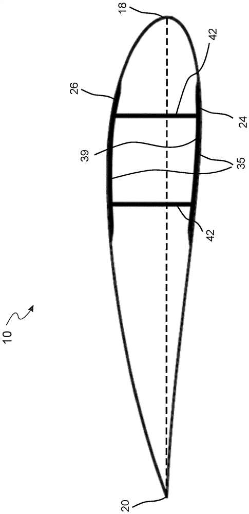
[0071] figure 2 A schematic diagram of an exemplary wind turbine blade 10 is shown. The wind turbine blade 10 has a shape with a conventional wind turbine blade with a rheal end and a tip end, and includes the root region 30 closest to the hub, the molding or airfoil region 34, which is farther away from the hub, and at the root The transition zone 32 between the region 30 and the airfoil region 34. The blade 10 includes a...


PUM

PropertyMeasurementUnit
lengthaaaaaaaaaa
widthaaaaaaaaaa
lengthaaaaaaaaaa

Abstract

Disclosed is a method for manufacturing a reinforced shell part for a wind turbine blade (10). The method comprises, providing a shell having an (39a), optionally arranging a plurality of fibre layers on the inner surface (39a) of the shell to form a base part of a reinforced section, providing a preform of a first inlay, arranging the preform of the first inlay on the inner surface of the shell and / or on the base part of the reinforced section, providing a preform of a second inlay, arranging the preform of the second inlay on the inner surface of the first shell part and / or on the base part of the reinforced section, arranging at least one pultrusion layer on the preform of the first inlay, the preform of the second inlay, and the inner surface of the shell and / or the base part of the reinforced section, wherein the pultrusion layer comprises a plurality of pultruded members grouped together, the pultrusion layer has a proximal edge, a distal edge and two opposing lateral edges, and the pultrusion layer is arranged in a spanwise direction of the blade such that the proximal edge of the pultrusion layer is arranged on the preform of the first inlay, and the distal edge of the pultrusion layer is arranged on the preform of the second inlay.

Description

Technical field [0001] The present disclosure relates to the manufacture of the enhanced housing member of the wind turbine blade. More specifically, the present disclosure relating to the field of enhanced housing members having a pultrusion layer and a preform for the inlay (such as a preform) for the first inlay and / or second inlay). Background technique [0002] The wind turbine blade of the fiber reinforced polymer, and in particular the air kinetic housing of the wind turbine blade, typically includes an enhanced section, the enhancement section including a pultrusion layer extending in the exhibition direction of the wind turbine blade. During the manufacturing of the wind turbine blade, two half-housings were fabricated by laying a glass fiber pad to form a half-shell, and a carbon fiber pad is laid on the top of the glass fiber pad to form a pultrusion layer. Alternatively, an additional base layer of a glass fiber forming a base member is laid before the pultrusion la...

Claims


Application Information

Patent Timeline
Patent Type & Authority Applications(China)
IPC IPC(8): B29C70/68B29D99/00
CPCB29C70/68B29C70/682B29D99/0028Y02E10/72Y02P70/50B29L2031/085F03D1/0675F05B2280/6003
Inventor M·伦德-拉弗里克K·杰斯帕森K·L·马德森
Owner LM WIND POWER AS
Features
  • R&D
  • Intellectual Property
  • Life Sciences
  • Materials
  • Tech Scout
  • Unparalleled Data Quality
  • Higher Quality Content
  • 60% Fewer Hallucinations
Learn More