Automatic mortar spraying machine

A spraying machine and mortar technology, applied in the direction of construction, building construction, etc., can solve the problems of workers' randomness in operation, uneven spraying quality, waste of steel pipes and wood, etc., and achieve high construction efficiency, uniform spraying, and improved The effect of work efficiency

Inactive Publication Date: 2022-01-04
东台昊之峰建设工程有限公司
View PDF12 Cites 2 Cited by
  • Summary
  • Abstract
  • Description
  • Claims
  • Application Information

AI Technical Summary

Problems solved by technology

[0002] In current construction projects such as building construction, bridge construction, elevated road construction, water conservancy facility construction and other fields, it is necessary to apply cement mortar support layer on the wall surface after the construction of the main frame or wall of the building is completed. The current mortar application is basically It is done manually, and the mixed cement mortar is transported to the construction site for wall work. For high construction sites, scaffolding needs to be erected. First, steel pipes and wood are wasted. Second, there are potential safety hazards. Third, labor efficiency is low. Labor intensity is high; the existing mortar spraying machines have the advantages of wide spraying range, high construction efficiency, and strong maneuverability, and are widely used in spraying operations in various industries. However, during the use of spraying machines, workers have high labor intensity and low construction efficiency. Workers hold the spray head to control the position and thickness of the spraying. The workers operate more randomly, with different proficiency levels, and the spraying quality is uneven, which causes great difficulties for the subsequent smoothing of the putty.

Method used


Image

  • Automatic mortar spraying machine
  • Automatic mortar spraying machine
  • Automatic mortar spraying machine

Examples


Embodiment 1

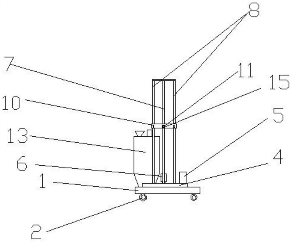
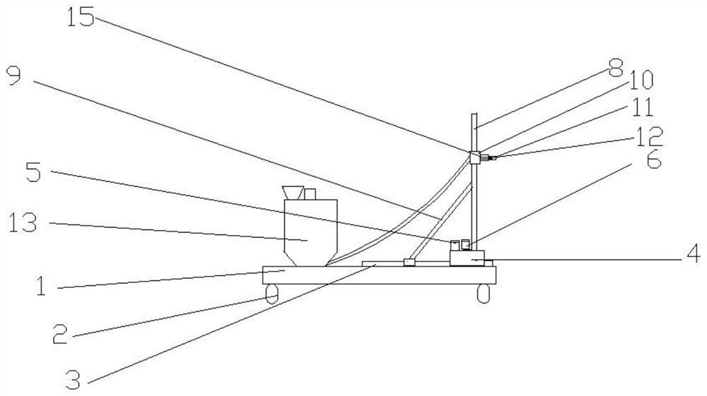
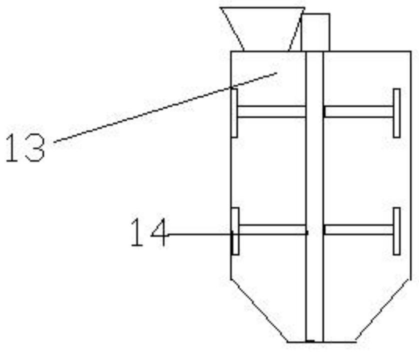
[0019] like Figure 1 to Figure 4 As shown, an automatic mortar spraying machine includes a base plate 1, a spray gun 11, a diaphragm pump, a controller and a display screen. A plurality of wheels 2 are arranged below the base plate 1, and one of the wheels 2 is connected to the first motor through gears. , the bottom plate 1 is provided with a stirring tank 13, the stirring tank 13 communicates with the spray gun 11 through a pipeline, the spray gun 11 communicates with the diaphragm pump, the base plate 1 is also provided with a guide rail 3, and the guide rail 3 is provided with There is a slide 4, the slide 4 is connected with the second motor 5, the slide 4 is provided with a lead screw 7, the lead screw 7 is connected with the third motor 6, the lead screw 7 is provided with a slide Block 10, described slide block 10 is provided with sensor 15 and spray gun 11, and described spray gun 11 is connected with rotary cylinder 12, and described controller is connected with des...

Embodiment 2

[0030] An automatic mortar spraying machine, comprising a base plate 1, a spray gun 11, a diaphragm pump, a controller and a display screen, a plurality of wheels 2 are arranged below the base plate 1, and one of the wheels 2 is connected to a first motor through a gear, and the The bottom plate 1 is provided with a stirring tank 13, the stirring tank 13 communicates with the spray gun 11 through a pipeline, the spray gun 11 communicates with the diaphragm pump, and the base plate 1 is also provided with a guide rail 3, and the guide rail 3 is provided with a sliding seat 4. The slider 4 is connected to the second motor 5, the slider 4 is provided with a screw 7, the screw 7 is connected to the third motor 6, the screw 7 is provided with a slider 10, Described slide block 10 is provided with sensor 15 and spray gun 11, and described spray gun 11 is connected with rotary cylinder 12, and described controller is connected with described diaphragm pump, spray gun 11, display scree...


PUM


Abstract

A plurality of wheels are arranged below a bottom plate, one wheel is connected with a first motor through a gear, a stirring tank is arranged on the bottom plate, the stirring tank is communicated with a spray gun through a pipeline, the spray gun is communicated with a diaphragm pump, a guide rail is further arranged on the bottom plate, a sliding seat is arranged on the guide rail, the sliding seat is connected with a second motor, and a lead screw is arranged on the sliding seat. The lead screw is connected with the third motor, a sliding block is arranged on the lead screw, a sensor and a spray gun are arranged on the sliding block, the spray gun is connected with the rotating air cylinder, and the controller is connected with the diaphragm pump, the spray gun, the display screen, the first motor, the second motor, the third motor, the rotating air cylinder and the sensor. The device can complete spraying of indoor and outdoor curved surfaces and vertical wall surfaces of a building, it is guaranteed that the distance between the spraying gun and the sprayed wall surface is fixed, the spraying thickness is controllable, spraying is uniform, the construction operation efficiency is high, the later mortar slicking and polishing workload is reduced, manual operation is reduced, the working efficiency is improved, the operation difficulty is reduced, and the labor cost is reduced.

Description

technical field [0001] The invention relates to the field of construction machinery, in particular to a mortar spraying machine. Background technique [0002] In current construction projects such as building construction, bridge construction, elevated road construction, water conservancy facility construction and other fields, it is necessary to apply cement mortar support layer on the wall surface after the construction of the main frame or wall of the building is completed. The current mortar application is basically It is done manually, and the mixed cement mortar is transported to the construction site for wall work. For high construction sites, scaffolding needs to be erected. First, steel pipes and wood are wasted. Second, there are potential safety hazards. Third, labor efficiency is low. Labor intensity is high; the existing mortar spraying machines have the advantages of wide spraying range, high construction efficiency, and strong maneuverability, and are widely u...

Claims


Application Information

Patent Timeline
Patent Type & Authority Applications(China)
IPC IPC(8): E04F21/08E04F21/16
CPCE04F21/08E04F21/16
Inventor 徐飞
Owner 东台昊之峰建设工程有限公司
Why Eureka
Try Eureka