
Vapor chamber

A technology of temperature chambers and substrates, applied in cooling/ventilation/heating renovation, electrical components, lighting and heating equipment, etc., which can solve the problems of poor heat transfer efficiency, scattered working fluid, and easy mutual interference.

Pending Publication Date: 2022-01-11
AURAS ELECTRONICS SCI & TECH IND KUNSHAN
View PDF0 Cites 0 Cited by
  • Summary
  • Abstract
  • Description
  • Claims
  • Application Information

AI Technical Summary

Problems solved by technology

However, the existing heat dissipation elements still have the problem that the working fluid and the vapor flow flow in the same channel space and are easy to interfere with each other, especially when the shear stress of the vapor flow is greater than the surface tension of the working fluid, the The working fluid will be scattered, or even the working fluid will entrain the vapor flow and flow backwards, resulting in poor heat transfer efficiency

Method used


Image

  • Vapor chamber
  • Vapor chamber
  • Vapor chamber

Examples


Embodiment Construction

[0074] The implementation of the present invention will be described below by means of specific specific examples, and those who are familiar with this technology can easily understand other advantages and effects of the present invention from the content disclosed in this description, and can also use other different specific examples implement or apply.

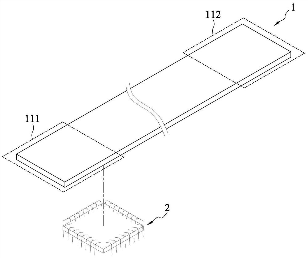
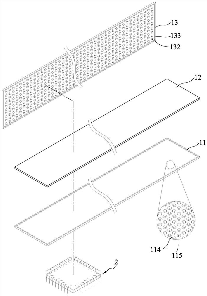
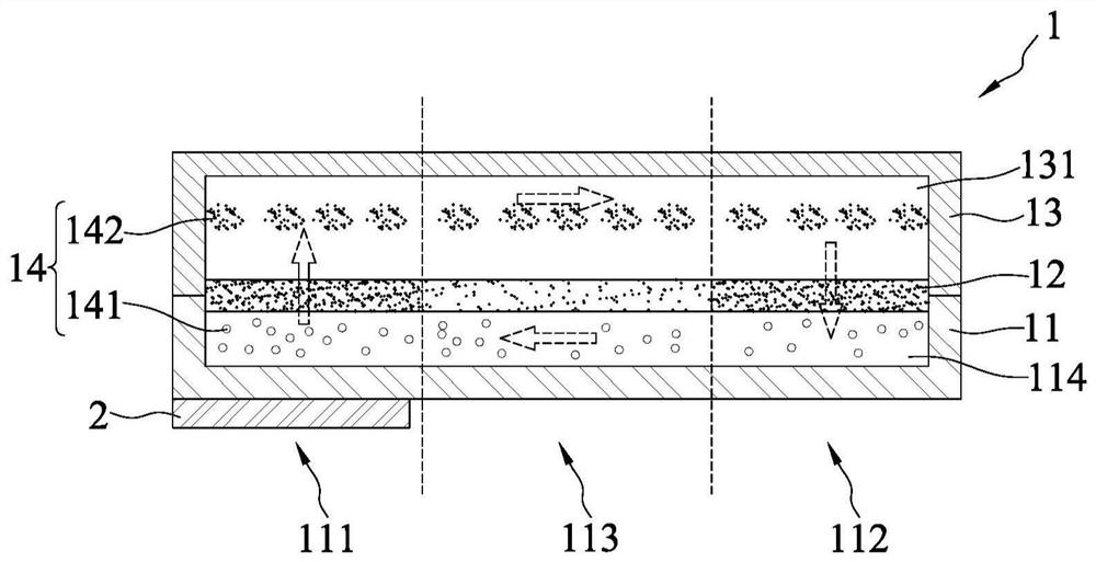
[0075] see Figure 1A , Figure 1B , figure 2 and image 3 , the vapor chamber 1 of the present invention includes a first substrate 11, a flow guide layer 12 and a second substrate 13, and the vapor chamber 1 of the present invention can contact at least one heat source 2, and the vapor chamber 1 can define a corresponding An evaporation area 111 and at least one condensation area 112 of the heat source 2 , and an adiabatic area 113 except the evaporation area 111 and the condensation area 112 . Hereinafter, a heat source 2 , an evaporation zone 111 , a condensation zone 112 and an adiabatic zone 113 are used for illus...


PUM

PropertyMeasurementUnit
Widthaaaaaaaaaa
Thicknessaaaaaaaaaa
Depthaaaaaaaaaa

Abstract

The invention provides a vapor chamber which comprises a base plate, a flow guide layer and a plurality of liquid channels. The flow guide layer is arranged on the base plate and is provided with a first hole and a second hole; and at least one liquid channel is formed between the base plate and the flow guide layer. The vapor chamber defines an evaporation area corresponding to a heating source and at least one condensation area, and the size of the first hole corresponding to the evaporation area and the condensation area is different from the size of the second hole corresponding to the non-evaporation area and the non-condensation area.

Description

technical field [0001] The invention relates to the field of heat dissipation, in particular to a uniform temperature plate. Background technique [0002] According to the demands of modernization, computers and various electronic devices are developing rapidly and their performance is constantly improving. However, in the process, heat dissipation problems caused by high-performance hardware also follow. Generally speaking, computers and various electronic devices usually use heat dissipation components to dissipate heat. For example, heat dissipation paste or heat sinks are attached to the electronic components to be dissipated to absorb and dissipate heat. However, the effect of this heat dissipation method is limited, so a heat dissipation element using phase change of the working fluid to promote heat conduction has been developed. [0003] The above-mentioned heat dissipation element achieves the purpose of heat transfer through the phase change and flow direction of ...

Claims


Application Information

Patent Timeline
IPC IPC(8): F28D15/04H05K7/20
CPCF28D15/046F28D15/0233H05K7/20336
Inventor 陈志伟张天曜郭哲玮庄翔智
Owner AURAS ELECTRONICS SCI & TECH IND KUNSHAN
Features
  • Generate Ideas
  • Intellectual Property
  • Life Sciences
  • Materials
  • Tech Scout
  • Unparalleled Data Quality
  • Higher Quality Content
  • 60% Fewer Hallucinations
Learn More