Novel edge trimming machine

An edge cutting machine, a new technology, applied in metal processing and other directions, can solve the problems of high cost, high noise and vibration, high power consumption, etc., and achieve the effect of low cost, low noise and vibration

Pending Publication Date: 2022-01-14
台州市坚特机械设备有限公司
0 Cites 0 Cited by

AI-Extracted Technical Summary

Problems solved by technology

The current edge trimming machine is usually driven by hydraulic pressure or air pressure. Hydraulic drive needs to be equipped with a hydraulic station, which is costly. Pneumatic driv...

Abstract

The invention discloses a novel edge trimming machine. The edge trimming machine comprises a rack and is characterized in that an edge trimming device is arranged on the upper side of the rack and comprises a lower workbench and an upper supporting table, a liftable movable workbench is arranged between the lower workbench and the upper supporting table, a double-output-shaft gear motor is arranged on the upper side of the upper supporting table, eccentric bearings are arranged on output shafts at the two ends of the double-output-shaft gear motor respectively, the output shafts of the double-output-shaft gear motor are fixedly connected with shaft holes in inner rings of the eccentric bearings, connecting rods are fixedly connected to outer rings of the eccentric bearings, and the lower ends of the connecting rods are movably hinged to the movable workbench; adjusting devices are arranged on the connecting rods. The double-output-shaft gear motor and the eccentric bearings are used for driving the movable workbench and an upper cutting die to conduct shearing action, and the machine has the advantages of low cost and small noise and vibration.

Application Domain

Metal working apparatus

Technology Topic

Electric machineryEngineering +3

Image

  • Novel edge trimming machine
  • Novel edge trimming machine

Examples

  • Experimental program(1)

Example Embodiment

[0010] The following descriptions are only preferred embodiments of the present invention, and do not limit the protection scope of the present invention. The present invention will be further described below in conjunction with the accompanying drawings and embodiments.
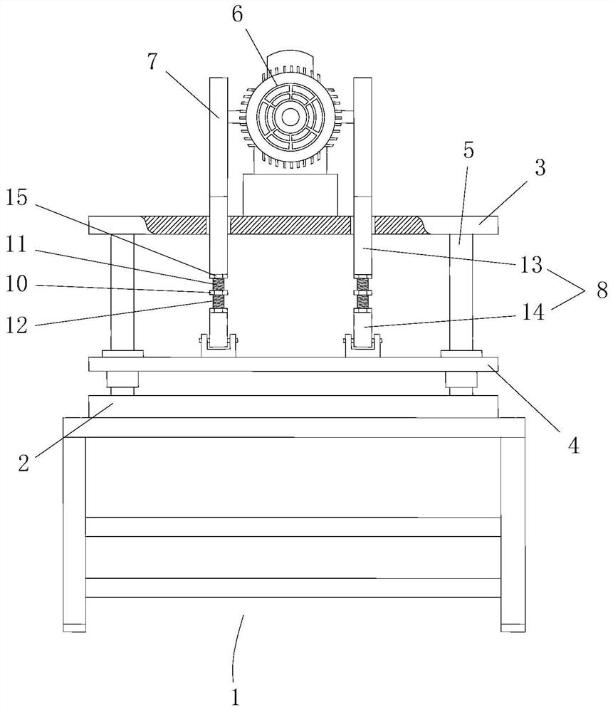
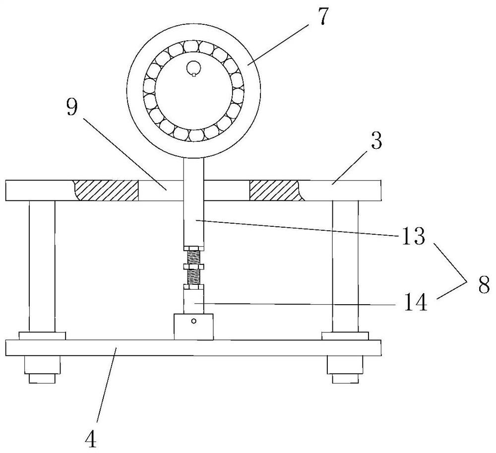
[0011] Examples, see Figure 1 to Figure 2 Shown: a kind of novel trimming machine, comprises frame 1, and the upper side of described frame 1 is provided with trimming device, and described trimming device comprises lower workbench 2 and upper supporting platform 3, lower workbench 2 and A liftable movable workbench 4 is arranged between the upper support platform 3, wherein the four corners between the lower workbench 2 and the upper support platform 3 are respectively provided with piston rods 5, and the four corners of the movable workbench 4 Piston barrels are respectively provided and are movably socketed on the four piston rods 5; the upper side of the upper support platform 3 is provided with a double output shaft reduction motor 6, and the output shafts at both ends of the double output shaft reduction motor 6 are respectively equipped with eccentric bearings 7. The output shaft of the double output shaft deceleration motor 6 is fixedly connected with the shaft hole of the inner ring of the eccentric bearing 7, and the outer ring of the eccentric bearing 7 is fixedly connected with a connecting rod 8, and the lower end of the connecting rod 8 passes through the upper supporting platform 3 and then connects with the The movable workbench 4 is movable and hinged, and the upper support platform 3 is provided with a hole 9 for the connecting rod 8 to pass through and reserves a swing space; the lower side of the movable workbench 4 is provided with an upper die, and the lower workbench 2 is provided with the lower cutting die that cooperates with upper cutting die. Described connecting rod 8 is provided with adjusting device, and adjusting device comprises main nut 10, and the upper and lower ends of main nut 10 are respectively fixedly connected with upper bolt 11 and lower bolt 12, and the threads on upper bolt 11 and lower bolt 12 are opposite to each other. Towards, the connecting rod 8 is divided into an upper connecting rod 13 and a lower connecting rod 14, the upper connecting rod 13 and the lower connecting rod 14 are provided with screw holes, the upper bolt 11 and the upper connecting rod 13 are screwed, and the lower bolt 12 and the lower connecting rod 14 are screwed, and the upper bolt 11 and the lower bolt 12 are also screwed with a fixed nut 15. After the double output shaft deceleration motor 6 is energized and started, the output shaft of the double output shaft deceleration motor 6 drives the inner ring of the eccentric bearing 7 to rotate, the inner ring drives the outer ring to make a circular motion, and the connecting rod 8 drives the movable worktable when the outer ring makes a circular motion 4 Make up and down movement, so that the upper knife mold can rise and fall repeatedly, and the upper knife mold and the lower knife mold cooperate to form repeated shearing actions. By turning the main nut, the length of the linkage can be adjusted to match the shearing action. The present invention utilizes double output shaft decelerating motor 6 and eccentric bearing 7 to drive the movable worktable 4 and the upper die for shearing action, and has the characteristics of low cost, low noise and vibration.

PUM

no PUM

Description & Claims & Application Information

We can also present the details of the Description, Claims and Application information to help users get a comprehensive understanding of the technical details of the patent, such as background art, summary of invention, brief description of drawings, description of embodiments, and other original content. On the other hand, users can also determine the specific scope of protection of the technology through the list of claims; as well as understand the changes in the life cycle of the technology with the presentation of the patent timeline. Login to view more.

Similar technology patents

Apparatus and method for low-density cellular wood plastic composites

InactiveUS20050067729A1less-expensivelow cost
Owner:STRANDEX CORP

Haptic trackball device

InactiveUS7710399B2simple actuatorlow cost
Owner:IMMERSION CORPORATION

Steering Arrangement for a Trailer

InactiveUS20110018231A1low cost
Owner:ZF FRIEDRICHSHAFEN AG

Classification and recommendation of technical efficacy words

  • Reduce vibration and noise
  • low cost

System and method for transmitting wireless digital service signals via power transmission lines

ActiveUS7929940B1reduce bandwidth requirementlow cost
Owner:NEXTEL COMMUNICATIONS

System and method for determination of position

InactiveUS20090149202A1low costreduce requirement
Owner:STEELE CHRISTIAN

Adaptive antenna optimization network

InactiveUS6961368B2low costminimal space
Owner:ERICSSON INC

Antenna device and method for attaching the same

ActiveUS20150138022A1low costimproved strength characteristic
Owner:NEC CORP
Why Eureka
Try Eureka