Multifunctional drilling machine for tunnel
A multi-functional, drilling machine technology, applied in the direction of rotary drilling rig, drilling equipment and method, earthwork drilling and mining, etc., can solve the problems of low drilling efficiency, harsh working environment, high labor intensity, etc., and improve the drilling efficiency. The effect of improving efficiency, improving the scope of application, and reducing labor intensity
- Summary
- Abstract
- Description
- Claims
- Application Information
AI Technical Summary
Problems solved by technology
Method used
Image

Examples
Embodiment 1
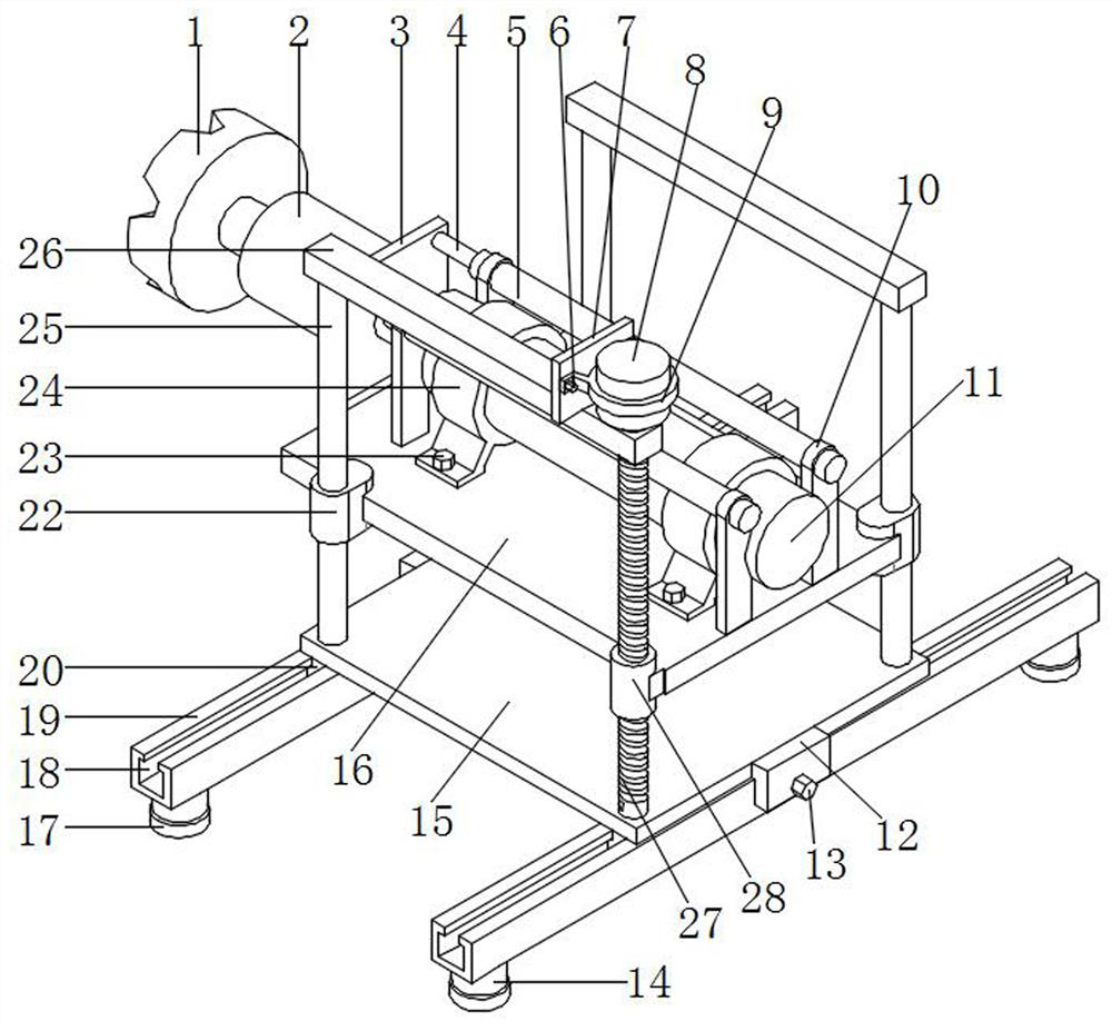
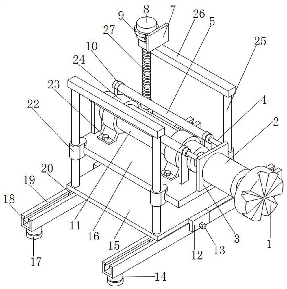
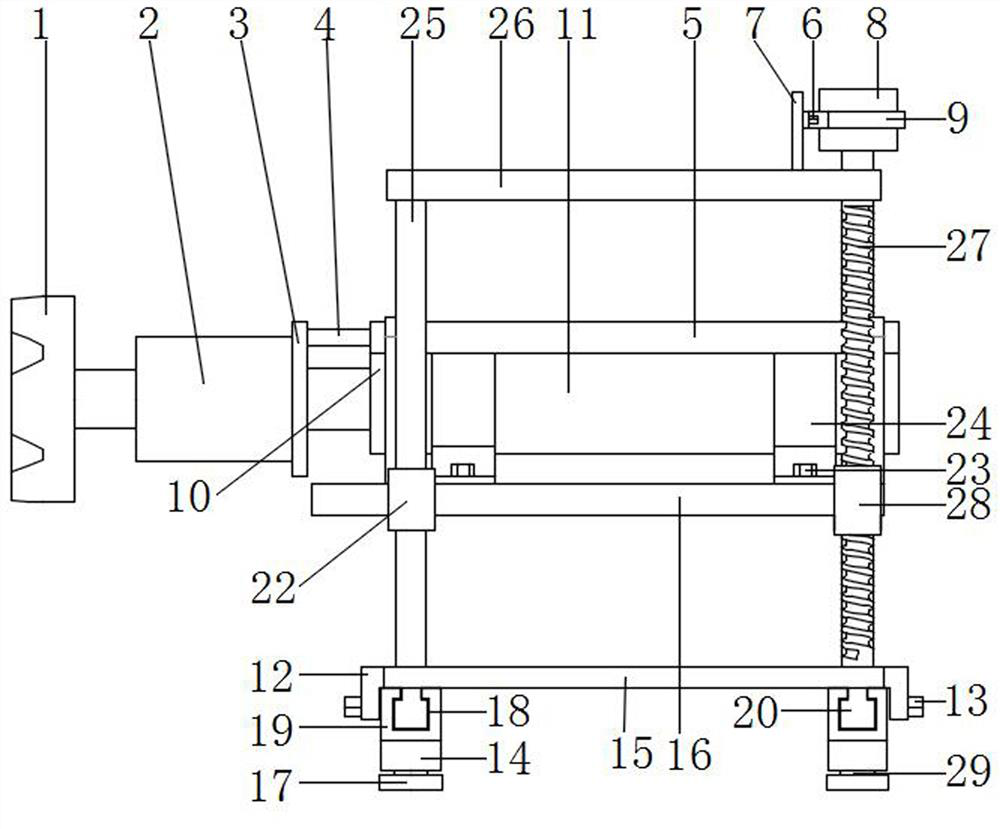
[0027] The main structure of this embodiment, such as Figure 1~3 As shown, it includes two parallel guide rails 19, and the two guide rails 19 are provided with T-shaped slide grooves 18, and the T-shaped slide grooves 18 are slidably connected with a T-shaped slide bar 20, and the upper end of the T-shaped slide bar 20 Connected with a base plate 15, the upper end of the base plate 15 is evenly connected with three guide rods 25 and a threaded rod 27 is connected with rotation, the upper end of the guide rod 25 is connected with a reinforcing rod 26, and the upper end of the threaded rod 27 passes through and is rotatably connected to strengthen Rod 26, threaded rod 27 passes through reinforcing rod 26 and is connected with second motor 8, described second motor 8 is detachably connected with reinforcing rod 26, guide rod 25 is slidably connected with sliding sleeve 22, and threaded rod 27 is connected with threaded sleeve 28 , the threaded sleeve 28 and the sliding sleeve 2...
Embodiment 2
[0030] In this embodiment, on the basis of the foregoing embodiments, support legs 14 are further added, such as figure 1 , figure 2 , image 3 , Figure 5 As shown, the lower end of the guide rail 19 is connected with a symmetrical support leg 14, and the support leg 14 is provided with a threaded hole 30, and the threaded hole 30 is threaded with a threaded column 29, and the lower end of the threaded column 29 is connected with an anti-slip pad 17 . The anti-skid pad 17 is adjusted in height under the threaded hole 30 through the threaded column 29, thereby ensuring the horizontal placement of the guide rail 19. Other parts of this embodiment are the same as those of the foregoing embodiment, and will not be repeated here.
Embodiment 3
[0032] In this embodiment, on the basis of the above embodiments, the structure of the hydraulic device 11 is further limited, such as Figure 1~3 As shown, the hydraulic device 11 is connected with two first support frames 24, and the first support frame 24 is connected with a first bolt 23, and the first bolt 23 passes through the first support frame 24 and is screwed to the base 16 . The hydraulic device 11 is detachably connected through the first bolt 23 to ensure rapid maintenance and disassembly of the hydraulic device 11 in the later stage. Other parts of this embodiment are the same as those of the foregoing embodiment, and will not be repeated here.
PUM
 Abstract
Description
Claims
Application Information
 - Generate Ideas
- Intellectual Property
- Life Sciences
- Materials
- Tech Scout
- Unparalleled Data Quality
- Higher Quality Content
- 60% Fewer Hallucinations
Browse by: Latest US Patents, China's latest patents, Technical Efficacy Thesaurus, Application Domain, Technology Topic, Popular Technical Reports.
© 2025 PatSnap. All rights reserved.Legal|Privacy policy|Modern Slavery Act Transparency Statement|Sitemap|About US| Contact US: help@patsnap.com