Waste cable processing system
A technology for processing systems and waste cables, which is applied in thin material processing, cable installation, cable installation devices, etc., can solve the problems of low efficiency of cables of different specifications, and the cable stripping device cannot be adapted, and achieves strong functionality and stripping. High efficiency and clean cable skin
- Summary
- Abstract
- Description
- Claims
- Application Information
AI Technical Summary
Problems solved by technology
Method used
Image

Examples
Embodiment 1
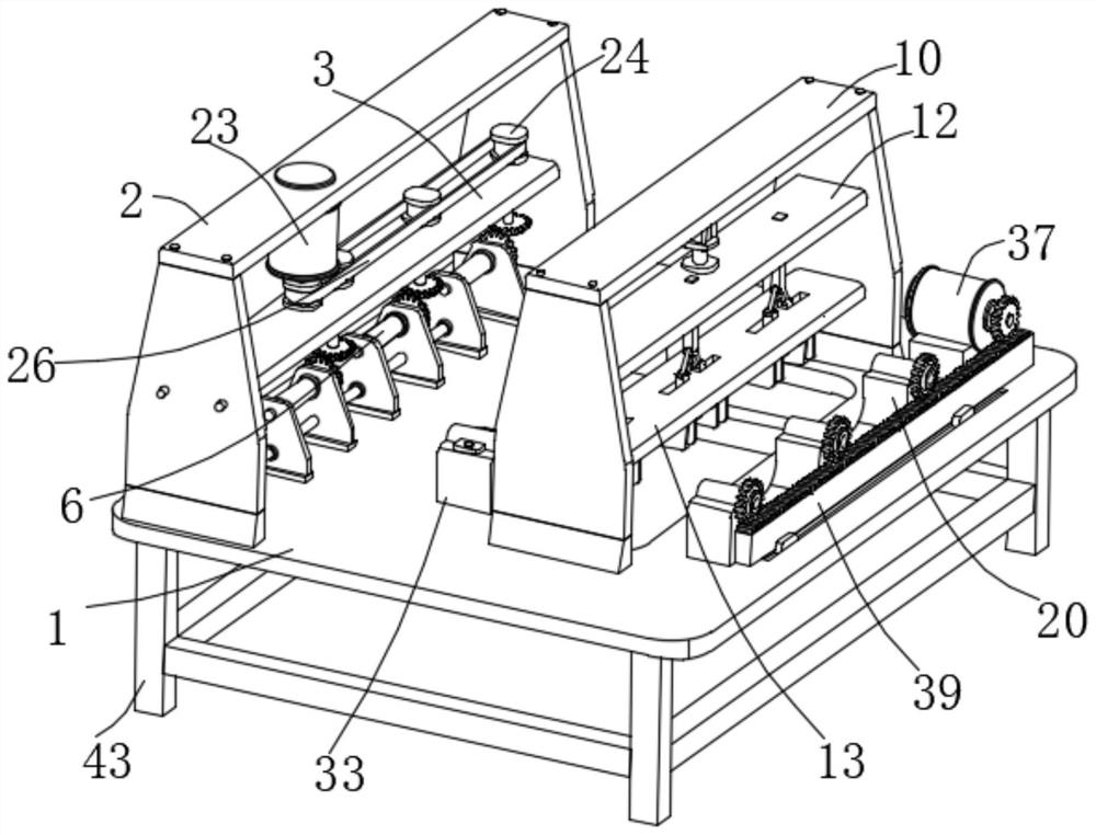
[0033] Such as figure 1 , figure 2 , image 3 , Figure 4 , Figure 5 , Figure 6As shown, this embodiment proposes a waste cable processing system, which includes a horizontally arranged bottom plate 1, a first fixed frame 2 is fixed vertically on the upper end of the bottom plate 1, and a first fixed frame 2 is installed horizontally below the first fixed frame 2. The connecting plate 3 fixedly connected to the inner side wall of the frame 2, the upper end surface of the connecting plate 3 is vertically provided with a plurality of rotating shafts 4 that rotate through the connecting plate 3, the upper end of the rotating shaft 4 is connected with a driving mechanism, and the driving mechanism includes a vertically fixed mounting on the first fixed The first motor 23 on the inner top surface of the frame 2, the outer walls of the upper ends of the plurality of rotating shafts 4 are all laterally fixedly sleeved with a driven pulley 24, and the outer wall of the output s...
Embodiment 2
[0035] The scheme in embodiment 1 is further introduced below in conjunction with specific working methods, see the following description for details:
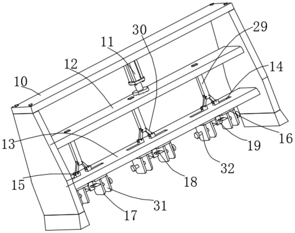
[0036] Such as figure 1 , image 3 , Figure 4 , Figure 5 , Figure 6 As shown, as a preferred embodiment, on the basis of the above-mentioned method, the pushing mechanism includes a second electric push rod 27 fixedly installed on the inner wall of the first fixed frame 2 laterally, and the free end of the second electric push rod 27 is fixedly installed laterally There is a push rod 28, the push rod 28 moves through multiple first side plates 7, the push rod 28 is fixed and runs through multiple second side plates 8, and the second electric push rod 27 simultaneously controls multiple second side plates 8 through the push rod 28 The movement of the second side plate 8 can be separated from the corresponding winding roller 6, so that the cable wound on the winding roller 6 can be easily taken out from the side, which is...
Embodiment 3
[0038] The schemes in Embodiment 1 and Embodiment 2 are further introduced below in conjunction with specific working methods, see the following description for details:
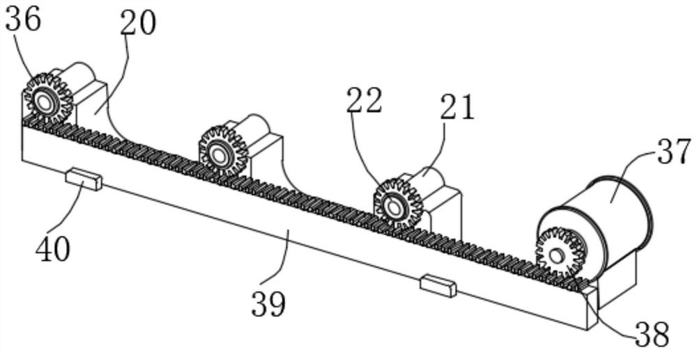
[0039] Such as figure 1 , figure 2 , Figure 4 , Figure 6 As shown, as a preferred embodiment, on the basis of the above-mentioned method, the power mechanism includes a driven gear 36 that is vertically fixedly sleeved on the outer wall of the sleeve 21, and a second motor 37 is fixedly mounted on the upper end surface of the bottom plate 1 laterally. The outer wall of the output shaft of the second motor 37 is vertically fixedly sleeved with a driving gear 38, and the driving gear 38 is meshed with a rack 39 that is horizontally installed on the upper end surface of the bottom plate 1 through a sliding mechanism, and the tooth rack 39 is meshed with the driven gear 36. The sliding mechanism includes a slider 40 fixedly installed on the outer wall of the rack 39. The upper end surface of the bottom pla...
PUM
 Abstract
Description
Claims
Application Information
 - Generate Ideas
- Intellectual Property
- Life Sciences
- Materials
- Tech Scout
- Unparalleled Data Quality
- Higher Quality Content
- 60% Fewer Hallucinations
Browse by: Latest US Patents, China's latest patents, Technical Efficacy Thesaurus, Application Domain, Technology Topic, Popular Technical Reports.
© 2025 PatSnap. All rights reserved.Legal|Privacy policy|Modern Slavery Act Transparency Statement|Sitemap|About US| Contact US: help@patsnap.com