Supercharge Your Innovation With Domain-Expert AI Agents!

Oil mist recovery device

A recovery device and oil mist technology, which is applied in combination devices, dispersed particle separation, chemical instruments and methods, etc., can solve the problems of corrosion, short residence time, short gas flow path, etc., to improve distribution uniformity and reduce airflow resistance. , the effect of improving filtration efficiency

Pending Publication Date: 2022-02-01
科瑞斯(江门)智能制造有限公司
View PDF1 Cites 0 Cited by
  • Summary
  • Abstract
  • Description
  • Claims
  • Application Information

AI Technical Summary

Problems solved by technology

[0006] (1) The air guide port of the oil mist recovery machine is located on the top of the second air chamber and directly connected to the second air chamber. After the gas is inhaled from the first air chamber, it is directly pushed upward into the second filter unit. The flow path of the air chamber is short, the residence time is short, the air conduction in the second air chamber is not uniform enough, and the utilization of the wind is still not sufficient;
[0007] (2) The turbine guide fan is directly exposed directly under the second filter unit, and the oil, water or dust filtered out by the second filter unit can easily enter the turbine guide fan, corroding or wearing the internal components of the turbine guide fan , affecting the service life of the turbo guide fan
[0008] The oil storage tank of the existing oil mist collector is set at the bottom of the frame, which is inconvenient to replace or clean the oil storage bottle

Method used


Image

  • Oil mist recovery device
  • Oil mist recovery device
  • Oil mist recovery device

Examples


Embodiment Construction

[0042] The specific implementation manner of the present invention will be described below in conjunction with the accompanying drawings.

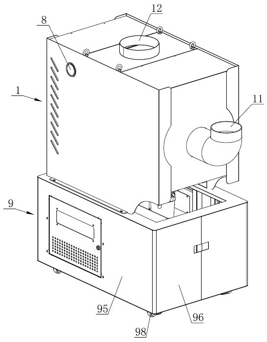
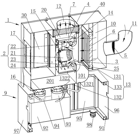
[0043] Such as figure 1 , figure 2 As shown, the recovery device of the present invention is arranged on the top surface of the chassis 9 .

[0044] Such as figure 1 , figure 2 As shown, the front side of the casing 1 of the recovery device is provided with an air intake pipe 11 , and the top surface of the casing 1 is provided with an air outlet 12 . Such as figure 2 As shown, a first filter element 5 is vertically arranged in the air intake pipe 11 along the radial direction, and the first filter element 5 is a metal filter screen, which can perform a first filtering process on the inhaled airflow.

[0045] Such as figure 2 As shown, a first partition 14 and a second partition 15 are arranged at intervals from front to back in the housing 1, and the first partition 14 and the second partition 15 divide the inner cavity of the h...


PUM


Abstract

The invention discloses an oil mist recovery device. An air inlet pipe is arranged on the side face of a shell, an air outlet is formed in the top face of the shell, a front air cavity and a rear air cavity which are communicated are formed in the shell, the front air cavity is communicated with the air inlet pipe, and the rear air cavity is communicated with the air outlet; and a fan is arranged in the rear air cavity, the periphery of the fan is sleeved with a housing, and a buffering cavity is formed between the housing and the fan and communicated with the rear air cavity. The housing is arranged outside the fan, on one hand, the housing provides a protection effect for the fan, the fan is prevented from being exposed under the air outlet, oil liquid, water liquid or dust and the like are prevented from entering the fan, internal elements of the fan are protected, and the service life of the fan is prolonged; on the other hand, the buffering cavity is formed in the periphery of the fan, airflow from the fan firstly enters the buffering cavity, is uniformly distributed in the buffering cavity and then flows into the rear air cavity from the air outlet channel, and the distribution uniformity of the airflow is better improved.

Description

technical field [0001] The invention relates to the technical field of air oil mist purification and recovery, in particular to an oil mist recovery device. Background technique [0002] During machining operations, it is often necessary to use various cutting oils or coolants to lubricate the tool and reduce the processing temperature of the workpiece, which will generate a large amount of oil mist, dust, oil smoke and smog in the working environment, causing physical fatigue of the operators on site. harm. The oil mist collector is mainly used to collect the oil mist, water mist or dust generated in mechanical processing, and through interception and filtration, the harmful substances in it are removed, and the metal cutting oil and other materials with recycling value are regenerated. Recycled, and finally discharged clean gas. [0003] Existing oil mist collectors usually have horizontal suction and horizontal gas outlet, that is, the gas is sucked in from the front si...

Claims


Application Information

Patent Timeline
Patent Type & Authority Applications(China)
IPC IPC(8): B01D50/20
Inventor 王默清
Owner 科瑞斯(江门)智能制造有限公司
Features
  • R&D
  • Intellectual Property
  • Life Sciences
  • Materials
  • Tech Scout
  • Unparalleled Data Quality
  • Higher Quality Content
  • 60% Fewer Hallucinations
Learn More