Downhole cable shearing device with energy storage power
A shearing device and cable technology, applied in drilling equipment, earthwork drilling, drill pipe, etc., can solve problems such as adverse effects of oil field production, cable wellhead fracture, cable shearing accidents, etc., to achieve stable and reliable shearing effect, well-designed , the effect of high work efficiency
- Summary
- Abstract
- Description
- Claims
- Application Information
AI Technical Summary
Problems solved by technology
Method used
Image
Examples
Embodiment 1
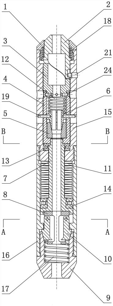
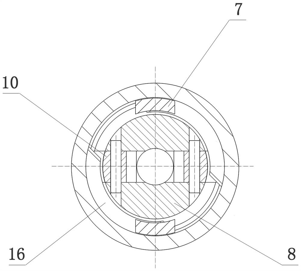
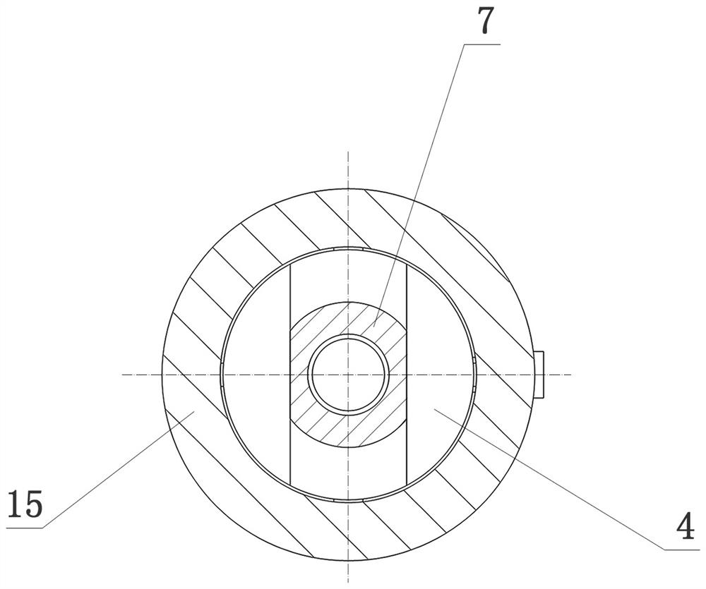
[0027] A double-blade downhole cable shearing device with energy storage power, such as Figure 1 to Figure 5 As shown, the upper joint 1, the impact rod 2, the conversion seat 3, the transmission sleeve 4, the slip seat 5, the split slip 6, the mandrel rod 7, the cutter seat 8, the lower joint 9, the cutting blade 10, the disc Spring group 11, slip spring 12, cutter spring 17, upper thrust bearing 13, lower thrust bearing 14, support spring 18, slip tube 15 and disc spring tube 16 constitute.
[0028] The slip cylinder 15 is connected up and down with the disc spring cylinder 16 to form an outer cylinder body, and the side wall of the slip cylinder 15 is radially and symmetrically provided with two strip-shaped slip limiting grooves 20. The upper joint 1 is connected to the upper end of the slip cylinder 15, the lower joint 9 is connected to the lower end of the disc spring cylinder 16, the striker rod 2, the conversion seat 3, the transmission sleeve 4, the The mandrel rod ...
Embodiment 2
[0035] A single-blade downhole cable cutting device with energy storage power, such as Figure 7 , Figure 8 and Figure 9 As shown, the upper joint 1, the impact rod 2, the conversion seat 3, the transmission sleeve 4, the slip seat 5, the split slip 6, the mandrel rod 7, the cutter seat 8, the lower joint 9, the cutting blade 10, the disc Spring group 11, slip spring 12, cutter torsion spring 25, upper thrust bearing 13, lower thrust bearing 14, support spring 18, slip tube 15, disc spring tube 16 and cutter frame 26 constitute.
[0036] Among them: the upper joint 1 described in this embodiment, the impact rod 2, the conversion seat 3, the transmission sleeve 4, the slip seat 5, the split slip 6, the mandrel rod 7. The lower joint 9, the disc spring set 11, the slip spring 12, the upper thrust bearing 13, the lower thrust bearing 14, the support spring 18, the slip cylinder 15 and the The structure of the disc spring barrel 16 and the cooperation between them are the sam...
PUM
 Abstract
Description
Claims
Application Information
 - R&D Engineer
- R&D Manager
- IP Professional
- Industry Leading Data Capabilities
- Powerful AI technology
- Patent DNA Extraction
Browse by: Latest US Patents, China's latest patents, Technical Efficacy Thesaurus, Application Domain, Technology Topic, Popular Technical Reports.
© 2024 PatSnap. All rights reserved.Legal|Privacy policy|Modern Slavery Act Transparency Statement|Sitemap|About US| Contact US: help@patsnap.com


