Supercharge Your Innovation With Domain-Expert AI Agents!

Touch panel, manufacturing method of touch panel and touch device

A touch panel and touch sensing electrode technology, applied in the input/output process of data processing, instruments, calculations, etc., can solve the problems of large width of the peripheral area, inability to reduce the size of the peripheral area, unfavorable general application, etc., to reduce Effects of width, good optical properties, and maintaining bendability

Pending Publication Date: 2022-02-25
TPK ADVANCED SOLUTIONS
View PDF0 Cites 0 Cited by
  • Summary
  • Abstract
  • Description
  • Claims
  • Application Information

AI Technical Summary

Problems solved by technology

[0003] However, there are still many problems to be solved in the process technology of the above-mentioned nano-scale materials
For example, when using nanowires to make touch electrodes, the touch electrodes and the lead wires made of metal in the peripheral area must be overlapped, and the overlapping area will cause the size of the peripheral area to be unable to be reduced, resulting in the width of the peripheral area Larger, unable to meet the narrow bezel requirements of the display
To give another example, touch electrodes made of nanowires often take into account optical effects, etc., so that the resistive capacitive loading (RC loading) is relatively large, which is not conducive to general application.

Method used


Image

  • Touch panel, manufacturing method of touch panel and touch device
  • Touch panel, manufacturing method of touch panel and touch device
  • Touch panel, manufacturing method of touch panel and touch device

Examples


Embodiment Construction

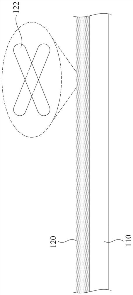
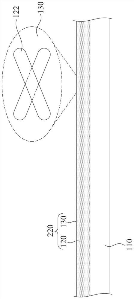
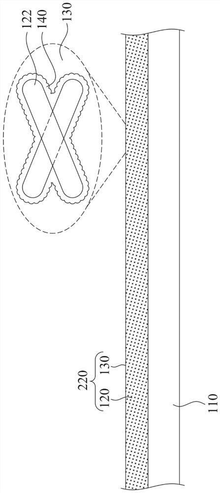
[0073] A number of implementations of the present disclosure will be disclosed below with the accompanying drawings. For the sake of clarity, many practical details will be described together in the following description. However, it should be understood that these practical details should not be used to limit the present disclosure. That is to say, in some embodiments of the present disclosure, these practical details are unnecessary, and thus should not be used to limit the present disclosure. In addition, for the sake of simplifying the drawings, some known and conventional structures and elements will be shown in a simple and schematic manner in the drawings. In addition, for the convenience of readers, the sizes of the elements in the drawings are not shown in actual scale.

[0074] Additionally, relative terms such as "lower" or "bottom" and "upper" or "top" may be used herein to describe one element's relationship to another element as shown in the figures. It will be...


PUM


Abstract

The invention discloses a touch panel, a manufacturing method of the touch panel and a touch device. The touch panel comprises a substrate, a peripheral lead and a touch sensing electrode. The substrate is provided with a display area, a peripheral area, a folding area and a non-folding area. The peripheral lead is arranged in the peripheral area of the substrate. The touch sensing electrode is arranged in the display area of the substrate and is provided with a first part located in the folding area and a second part located in the non-folding area. The touch sensing electrode is electrically connected with the peripheral lead and is provided with a latticed pattern formed by staggering a plurality of thin wires. Each of the peripheral lead and the touch sensing electrode comprises a plurality of conductive nanostructures and a film layer externally applied to the conductive nanostructures, and the interface between the conductive nanostructures in the second part of the peripheral lead and the touch sensing electrode and the film layer is substantially provided with a coating structure. Therefore, the resistance-capacitance type load value of the touch panel can be reduced, the narrow frame requirement of the display can be met, and the bending performance of the touch panel can be well maintained.

Description

technical field [0001] The present disclosure relates to a touch panel, a manufacturing method of the touch panel, and a touch device including the touch panel. Background technique [0002] In recent years, transparent conductors are often used in many display or touch-related devices because they can allow light to penetrate and provide proper conductivity at the same time. In general, transparent conductors can be thin films made of various metal oxides, such as indium tin oxide (ITO), indium zinc oxide (IZO), cadmium tin oxide (CTO) or aluminum-doped zinc oxide (AZO) thin films. However, these metal oxide thin films cannot meet the flexibility requirements of display devices. Therefore, a variety of flexible transparent conductors have been developed, for example, transparent conductors made of nano-scale materials. [0003] However, there are still many problems to be solved in the above-mentioned process technology of nano-scale materials. For example, when using na...

Claims


Application Information

Patent Timeline
IPC IPC(8): G06F3/041G06F3/044
CPCG06F3/0412G06F3/044G06F3/041G06F2203/04102G06F2203/04103G06F2203/04112
Inventor 余建贤丁紫君徐云国方建华陈明培
Owner TPK ADVANCED SOLUTIONS
Features
  • R&D
  • Intellectual Property
  • Life Sciences
  • Materials
  • Tech Scout
  • Unparalleled Data Quality
  • Higher Quality Content
  • 60% Fewer Hallucinations
Learn More