
Single-coil magnetic shielding low-power Hall thruster

A Hall thruster and magnetic shielding technology, which is applied in the direction of thrust reverser, machine/engine, and plasma utilization, can solve the problems of difficult design, complex thruster magnetic circuit design, increased excitation power consumption, etc., and achieve structural Compact, good heat dissipation, and the effect of reducing heat loss

Pending Publication Date: 2022-03-04
北京星辰空间科技有限公司
View PDF0 Cites 2 Cited by
  • Summary
  • Abstract
  • Description
  • Claims
  • Application Information

AI Technical Summary

Problems solved by technology

[0004] The magnetic circuit design of the existing multi-coil structure thruster is complex and difficult to design. At the same time, too many excitation coils will increase the excitation power consumption

Method used


Image

  • Single-coil magnetic shielding low-power Hall thruster
  • Single-coil magnetic shielding low-power Hall thruster
  • Single-coil magnetic shielding low-power Hall thruster

Examples


Embodiment Construction

[0023] In order to make the objects and advantages of the present invention clearer, the present invention will be further described below in conjunction with the examples; it should be understood that the specific examples described here are only for explaining the present invention, and are not intended to limit the present invention.

[0024] Preferred embodiments of the present invention are described below with reference to the accompanying drawings. Those skilled in the art should understand that these embodiments are only used to explain the technical principle of the present invention, and are not intended to limit the protection scope of the present invention.

[0025] It should be noted that, in the description of the present invention, terms such as "upper", "lower", "left", "right", "inner", "outer" and other indicated directions or positional relationships are based on the terms shown in the accompanying drawings. The direction or positional relationship shown is ...


PUM


Abstract

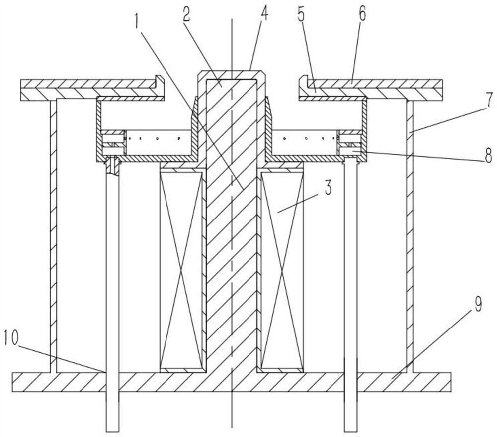
The invention relates to a single-coil magnetic shielding low-power Hall thruster which comprises an inner magnetic conductive column, an inner magnetic pole, a magnet exciting coil, an inner ceramic discharge channel, an outer ceramic discharge channel, an outer magnetic pole, an outer magnetic conductive column, an anode and a magnetic conductive bottom plate. Heat consumption generated by eddy current in a magnetic circuit is reduced by adopting a single-turn coil winding, and the magnetic field of the magnetic circuit is adjustable; the magnetic flux required by the low-power thruster can be processed, heat consumption which is continuously increased in the magnet exciting coil can be reduced to the maximum extent, and the thruster is small in size and has the advantages of being good in heat dissipation, compact in structure, high in performance and long in service life.

Description

technical field [0001] The invention relates to the technical field of Hall thrusters, in particular to a single-coil magnetically shielded low-power Hall thruster. Background technique [0002] Hall thruster is currently a typical electric propulsion device in the world. The main structure of Hall thruster includes: cathode assembly, anode assembly, magnetic circuit assembly, gas circuit assembly and installation assembly. The smaller the power of the thruster, the larger the area / volume ratio of the corresponding discharge channel, which means that more charged particles will be deposited on the wall of the channel, resulting in energy loss and reducing the performance of the thruster, and at the same time causing the thermal effect of the thruster. Therefore, compared with mature kilowatt-level power thrusters, the performance decline of low-power Hall thrusters is more obvious. [0003] In order to improve the performance, various structures of Hall thrusters have been ...

Claims


Application Information

Patent Timeline
IPC IPC(8): F03H1/00
CPCF03H1/0081
Inventor 潘海林姚艳温凡
Owner 北京星辰空间科技有限公司
Learn More