Check patentability & draft patents in minutes with Patsnap Eureka AI!

Industrial robot stacking workstation

A technology of industrial robots and workstations, applied in stacking, unstacking, transportation and packaging of objects, etc., can solve the problems of bulky volume, and achieve the effects of small volume, easy installation, transportation and debugging, and simple structure

Pending Publication Date: 2022-03-08
广东三向智能科技股份有限公司
View PDF6 Cites 1 Cited by
  • Summary
  • Abstract
  • Description
  • Claims
  • Application Information

AI Technical Summary

Problems solved by technology

[0004] The purpose of the present invention is to provide an industrial robot palletizing workstation to solve the existing problem of bulky

Method used


Image

  • Industrial robot stacking workstation
  • Industrial robot stacking workstation
  • Industrial robot stacking workstation

Examples


Embodiment 1

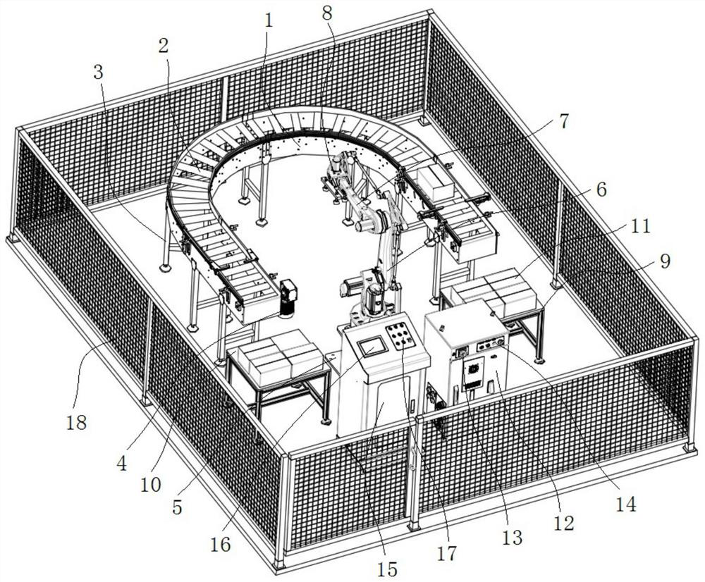
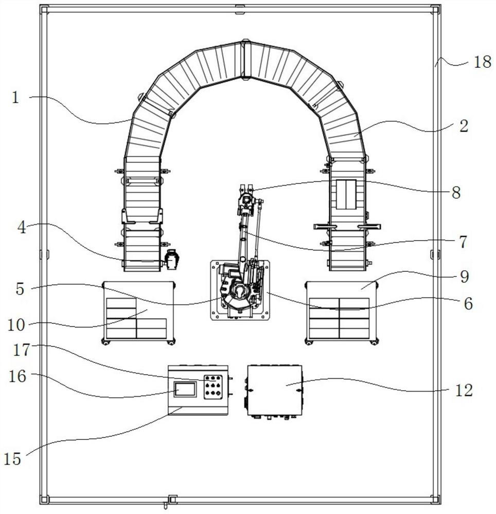
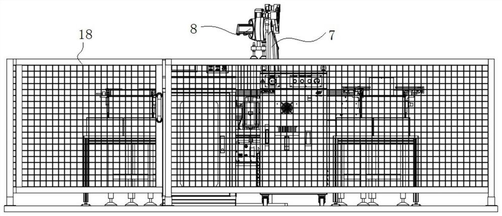
[0028] see Figure 1-5 As shown, the present invention is an industrial robot palletizing workstation, including a U-shaped installation frame 1, a U-shaped conveying line 2 and a frequency conversion motor 4, the U-shaped conveying line 2 is installed inside the U-shaped installing frame 1, and the U-shaped conveying line 2 The type can be a roller conveyor line, or a PVC flat belt conveyor line or a plate chain conveyor line. The trajectory of its conveying materials is like a "U-shaped word". Cooperate with the U-shaped conveying line 2, which can make the U-shaped conveying line 2 rotate forward and reverse, so as to realize circular palletizing. Several installation brackets 3 are installed on the lower surface of the U-shaped installation frame 1, and one end of the U-shaped conveying line 2 is placed A first palletizing platform 9 is installed, a second palletizing platform 10 is placed at the other end of the U-shaped conveying line 2, and a number of palletizing objec...

Embodiment 2

[0034] see Figure 1-5 As shown, the present invention is an industrial robot palletizing workstation, and its use method is as follows: first, the corresponding palletizing fixture can be selected according to the training object. If the training object is a carton, a vacuum suction gripper or a Splint-type manipulator claws, if it is bagged, use grabbing-type manipulator claws to fix the palletizing fixture on the end joint 7 of the industrial robot 6; place the palletizing objects 11 on the first palletizing platform 9 and the second On the palletizing platform 10, there are corresponding scales on the first palletizing platform 9 and the second palletizing platform 10, and they are placed according to the original position and size; after checking that the circuit and the gas circuit are normal, power on, start the industrial robot 6, and manually coordinate point calibration of the industrial robot 6; after completion, press the start button of the electrical control cabi...


PUM


Abstract

The invention discloses an industrial robot stacking workstation, and relates to the technical field of industrial robot automatic stacking. The stacking device comprises a U-shaped mounting frame, a U-shaped conveying line and a variable frequency motor, and is characterized in that the U-shaped conveying line is mounted in the U-shaped mounting frame, the variable frequency motor is mounted on one surface of the U-shaped mounting frame and matched with the U-shaped conveying line, a plurality of mounting supports are mounted on the lower surface of the U-shaped mounting frame, and a first stacking table is mounted at one end of the U-shaped conveying line; a second stacking table is placed at the other end of the U-shaped conveying line, a plurality of stacking objects are placed on the upper surface of the first stacking table and the upper surface of the second stacking table, and an industrial robot base is installed between the first stacking table and the second stacking table. Through the variable frequency motor structure, the U-shaped conveying line can rotate forwards and backwards, so that circulating stacking can be achieved, meanwhile, through the guardrail structure, the work station area is divided, training can be conducted in batches, and it is prevented that too many people squeeze in for operation, and other dangers are generated.

Description

technical field [0001] The invention belongs to the technical field of automatic palletizing of industrial robots, in particular to an industrial robot palletizing workstation. Background technique [0002] Stack stacker is to put cartons loaded into containers on pallets according to a certain arrangement for automatic stacking. It can be stacked up for multiple layers and then rolled out to facilitate forklift operation to the warehouse for storage. This equipment adopts PLC+touch screen control to realize intelligent operation and management, which is simple and easy to master. Can greatly reduce labor and reduce labor intensity. The palletizer is a device that automatically stacks the bags, cartons or other packaging materials delivered by the conveyor into stacks according to the working method required by the customer, and transports the stacked materials. The automatic palletizer is a machine-electrical integration High-tech products, medium and low-position palleti...

Claims


Application Information

Patent Timeline
Patent Type & Authority Applications(China)
IPC IPC(8): B65G57/03B65G61/00
CPCB65G57/03B65G61/00Y02P70/10
Inventor 伊洪良刘学忠张灿明
Owner 广东三向智能科技股份有限公司
Features
  • R&D
  • Intellectual Property
  • Life Sciences
  • Materials
  • Tech Scout
  • Unparalleled Data Quality
  • Higher Quality Content
  • 60% Fewer Hallucinations
Learn More