Ultrasonic splicing machine for magic tapes
An ultrasonic welding and ultrasonic technology, applied in the field of ultrasonic splicing machine for Velcro, can solve the problems of complex structure of splicing machine, poor splicing quality and inflexible use, etc., and achieve the effect of convenient welding and splicing processing.
- Summary
- Abstract
- Description
- Claims
- Application Information
AI Technical Summary
Problems solved by technology
Method used
Image

Examples
Embodiment Construction
[0022] In order to make the technical problems, technical solutions and beneficial effects to be solved by the present invention clearer, the present invention will be further described in detail below in conjunction with the accompanying drawings and embodiments. It should be understood that the specific embodiments described here are only used to explain the present invention, not to limit the present invention.
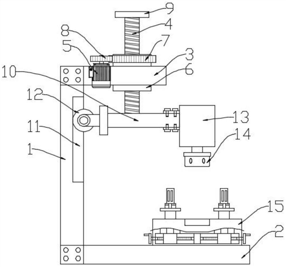
[0023] see figure 1 , in the embodiment provided by the present invention, an ultrasonic splicing machine for Velcro, comprising a support base plate 2, one side of the upper surface of the support base plate 2 is fixedly provided with a support side plate 1, and the top end of the support side plate 1 A support top plate 3 on the same side as the support bottom plate 2 is fixedly arranged, and the support top plate 3 is provided with a height adjustment assembly for adjusting the height of the lifting beam 10;
[0024] Specifically, one end of the lifting beam 10...
PUM
 Abstract
Description
Claims
Application Information
 - Generate Ideas
- Intellectual Property
- Life Sciences
- Materials
- Tech Scout
- Unparalleled Data Quality
- Higher Quality Content
- 60% Fewer Hallucinations
Browse by: Latest US Patents, China's latest patents, Technical Efficacy Thesaurus, Application Domain, Technology Topic, Popular Technical Reports.
© 2025 PatSnap. All rights reserved.Legal|Privacy policy|Modern Slavery Act Transparency Statement|Sitemap|About US| Contact US: help@patsnap.com