[0022] In order to make the technical problem solved by the present invention, the technical solution and the technical effects achieved are more clear, and the technical solutions of the embodiments of the present invention will be further described in connection with the accompanying drawings, which will be described in detail. Part of embodiments, not all embodiments. Based on the embodiments of the present invention, those skilled in the art are in the scope of the present invention without all other embodiments obtained without creative labor.
[0023] It should be noted that the component is referred to as "fixed to" another component, which can be directly in another component or may also exist. When a component is considered to be "connected" another component, it can be directly connected to another component or may have a homoa component. When a component is considered to be "set to" another component, it can be directly set on another component or may exist at the same time. The term "vertical", "horizontal", "left", "right", and similar expressions are only for illustrative purposes only.
[0024] It will also be noted that the description of "first", "second", etc., "first", "second", and the like, as described in the embodiment of the present invention, only to describe purposes, and cannot be understood as only or Imprepect its relative importance or implicitly indicated the number of technical features indicated. Thus, the features of "first", "second" are defined, and at least one of the features may be indicated or implicitly. In addition, the technical solution between the various embodiments can be combined with each other, but it must be based on those of ordinary skill in the art, and when the combination of technical solutions appear, the combination of this technical solution should be considered not present. It is not within the scope of the invention.
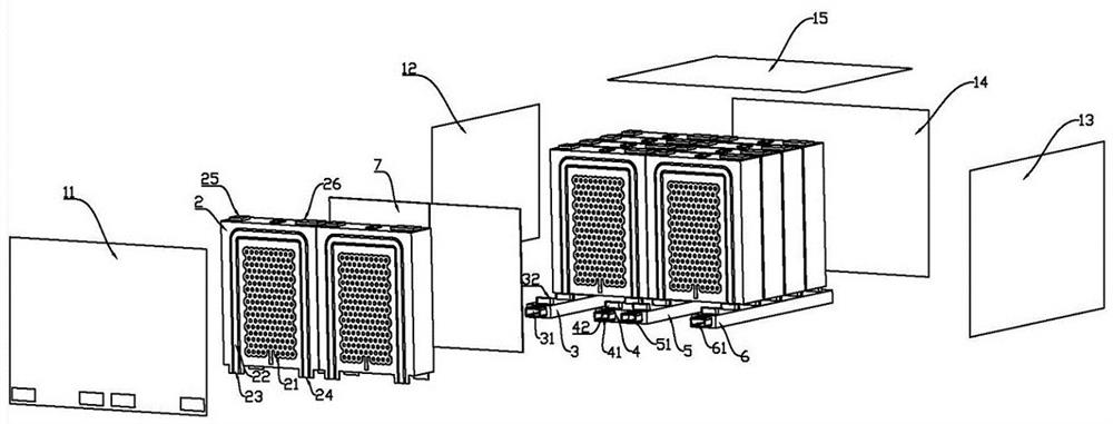
[0025] The present invention proposes a battery module, please refer to figure 1 As shown, the multi-column battery pack includes a housing, a plurality of column cores 2, and a plurality of water flow channels. The plurality of cells 2 are mounted in the housing to avoid collision and interference from the electrical cell 2.
[0026] The outer casing includes a front end plate 11, a first side plate 12, a second side plate 13, a rear end plate 14, and a cover plate 15, and the front end plate 11 parallel, the first side plate 12 and the first The second side plate 13 is parallel, the front end plate 11, the first side plate 12, the second side plate 13, and the rear end plate 14 are fastened to each other to connect the cavity of the hollow, cover the cover 15 hood outside the battery , Protect the core 2 protection.
[0027] The battery cell 2 is a square cell, and the first side surface 20 of the battery cell 2 is disposed on the heat superconducting line 21 and the refrigerant passage 22, and the heat superconducting line 21 has a heat transfer working article (not shown. ), The refrigerant passage 22 is a U-shaped surrounding the thermal superconducting line 21, and the first coupon 23 and the second coupling head 24 are respectively provided, the first coupling head 23 and the first plug. The two plug 24 protrudes from the outside of the housing.
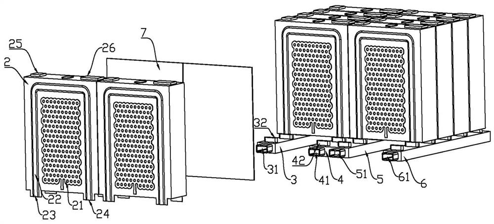
[0028] The water flow passage includes a first water flow passage 3, a second water flow passage 4, a third water flow passage 5, and a fourth water flow passage 6, and a water flow passage extends in a direction arranged in the electrical cell 2. The first water flow passage 3 is provided with a first inlet portion 31 and a first socket 32, and a first water flow passage is provided on the second water flow passage, the first coupling head 23 and the first socket. 32 corresponds to the second coupling head 24 corresponds to the second socket 42, and the battery cell 2 is inserted on the water flow passage by a jugged and the socket, and the battery cell 2 is sequentially plugged in this manner. On the water flow channel.
[0029] It should be noted that the heat transfer fluid filled in the thermal superconducting line 21 may be a gas or liquid or a mixture of gases, such as water, oil, alcohol, and the like. The electrical core housing filled with heat transfer is characterized by a good heat transfer rate and a good temperature. The suitable operating temperature of the battery cell 2 is between 20 and 50 ° C, and when the battery 2 temperature is higher than 50 ° C, the battery core 3 needs to be cooled, and therefore, the refrigerant enters the first water flow passage 3 from the inlet port 31, in the pressure Then, by the first plug 23 into the refrigerant passage 22, the heat of the heat superconductance line 21 absorbs the heat capacity of the battery core 2 is booted into the refrigerant passage 22, and the refrigerant in the refrigerant passage 22 is absorbed from the second water flow channel 4 after absorbing heat. The water outlet 41 flows out, thereby achieving the purpose of cooling; when the battery 2 temperature is less than 20 ° C, it is necessary to heat the battery, so that heat through hot water in the first water flow passage 3, flow through the refrigerant passage 22 after heat transfer The heat superconducting line 21 is supplied to heat the electrical core to achieve the purpose of warming.
[0030] The electrical core 2 upper refrigerant passage 22 is U-shaped surrounding the heat superconducting line 21, the refrigerant passage 22 and the heat superconducting line 21 show single-sided expansion, double-sided expansion or double-sided flat structure. The heat superconducting line 21 is a closed line, the shape of the closed thermal superconducting line, can be a hexagonal honeycomb shape that is connected to each other, or may be a four-sided shape in communication. In this embodiment, if figure 1 As shown, the refrigerant passage 22 and the heat superconducting line 21 are protruded from the surface of the cell 2, and protrude toward the cell 2.
[0031] Four openings are provided on the outer casing front panel 11, respectively correspond to the first inlet port 31, the first water opening 41, the second water port 51, and the second water outlet 61, and the water outlet and the effluent and external cooling. The system is connected to adjust the multi-column battery pack. The first water flow passage 3, the second water flow passage 4, the third water flow passage 5, and the fourth water flow passage 6 are parallel, in the present embodiment, the first inlet port 31, the first outlet 41, the second The water port 51 and the second water port 61 are in the same side, of course, in other embodiments, may be distributed on different sides, and the present invention is not limited thereto.
[0032] Please continue see figure 1 The plurality of cells 2 are inserted on the water flow passage, and the plurality of the cells 2 are provided with a flexible insulating layer 7, and the flexible insulating layer 7 is sandwiched between adjacent electrical cells; facilitating the battery 2 Transfer between heat transfer, the heat is distributed, and the flexibility and insulation of the flexible insulating layer 7 protect the cell 2 from collision and electrically conductive interference. In other embodiments, adjacent two cells can also be sandwiched with a flexible insulating layer 7 protective cell 2 from collision and conductive interference. Since the heat conductive silica gel has good conductive properties and insulating properties, thermally conductive silica gel is usually used as the main material of the flexible insulating layer. Flexible insulating layer 7 can also employ other flexible insulating materials or flexible phase change materials having insulating properties.
[0033] See figure 2In the water flow passage, one end is closed, and one end is closed, and the other end is provided with the water port or the water outlet. When used, the external cooling system passes the refrigerant to the first inlet port 31 and the second water port 51, and the refrigerant flows through it. After the refrigerant passage of the core of the core is, it flows out from the first water port 41 and the second water port 61. A seal ring (not shown) is provided in the socket, inserted into the socket, the sealing ring to sealed waterproof.
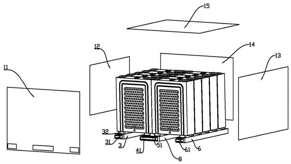
[0034] See image 3 The second water flow passage 4 and the third water flow passage 5 are adjacent to a cavity 8, the battery core 2 is inserted on the cavity 8, and the first water port 41 and the second water port 51 are combined. It is an inlet or water outlet. When the first effluent port 41 and the second water port 51 are combined into an outlet, the first inlet port 31 and the second water outlet 61 are inlet, the refrigerant from the first inlet port 31 and the second water port 61 into, respective The refrigerant passage flowing through the cavity 8 is finally flowing out from the water cavity 8; when the first outlet 41 and the second water port 51 are combined into an inlet, the first water port 31 and the second water port 61 For the water outlet, the refrigerant is entered in the cavity 8, each flows through the refrigerant passage of the cells in which the cell is located, and flows out of the first inlet port 31 and the second water port 61, respectively. The second water flow passage 4 and the third water flow passage 5 are incorporated into a cavity 8, and the first effluent port 41 and the second water port 51 can also be closed, and the refrigerant has entered from the first water port 31, flowing through it. After the refrigerant passage of the column core reaches the cavity 8, further flowing through the refrigerant passage of the other column, and finally flows from the second water port 61.
[0035] It should be noted that the water flow channel can be each independently parallel distribution, or may be disposed on a plate, it is understood that the water flow channel is disposed on the same plate, increasing the stability of the battery pack.
[0036] The present invention also proposes an energy storage system. The energy storage system includes a multi-column battery pack. Since the energy storage system employs all of the technical solutions of all of the above embodiments, all of the beneficial effects of at least the technical solution of the above embodiments is not repeated again. It will be appreciated that the energy storage system can be a wind power energy storage system, a solar energy storage system or a grid energy storage system.
[0037] The above embodiments are exemplified only to illustrate the principles and their efficacy of the present invention, rather than limiting the invention. Anyone familiar with this technique can modify or change the above-described embodiment without violating the spirit and scope of the invention. Thus, all of the technical fields have all the equivalent modifications or changes that are not departed under the spirit and technical idea of disclosure from the present invention, still covered by the equivalents of the present invention.