Intelligent manipulator for machining
A technology of mechanical processing and manipulators, which is applied in the direction of manipulators, manufacturing tools, claw arms, etc., can solve the problems of reducing the work efficiency of the staff, increasing the workload of the staff, and the complicated steps of fixture replacement, so as to simplify the steps of disassembly and assembly, reduce the Work load, effect of improving utilization
- Summary
- Abstract
- Description
- Claims
- Application Information
AI Technical Summary
Problems solved by technology
Method used
Image
Examples
Embodiment 1
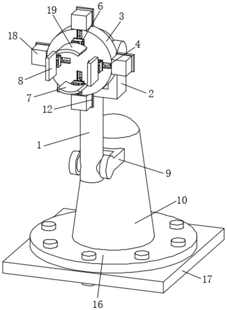
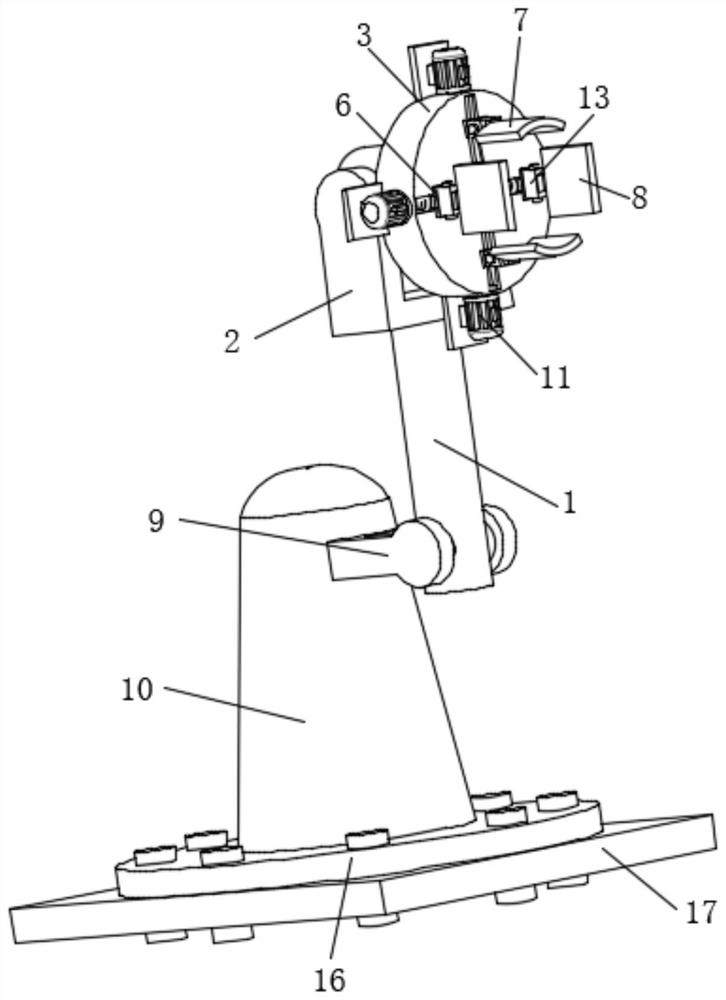
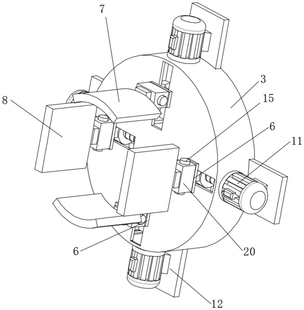
[0045] see figure 1 and figure 2 , an intelligent manipulator for mechanical processing, comprising a manipulator body 1, a No. 1 bracket 2 is fixedly installed on the upper end of the manipulator body 1, and a disk 3 is movably socketed on the outer wall of the No. 1 bracket 2 middle part, so that The inner wall of the disc 3 is evenly distributed with a number of movable devices 4, one end of the movable device 4 is connected with a reinforcement block 5, and the other end of the reinforcement block 5 is fixedly installed with a support block 6, and one side of the support block 6 is connected with a Fixture 19.
[0046] The fixture 19 includes a No. 1 fixture 7 and a No. 2 fixture 8. The No. 1 fixture 7 is adjacent to the No. 2 fixture 8. The outer wall of the support column 10 is fixedly connected with the No. 2 bracket 9. The mechanical arm body 1 The lower end and the No. 2 support 9 are movable sockets.
[0047] in. The installation of the No. 1 bracket 2 facilitat...
Embodiment 2
[0057] On the basis of Embodiment 1, please refer to 7-10, it also includes an adjustment assembly 16, the adjustment assembly 16 is arranged between the support column 10 and the base 17, and the adjustment assembly 16 includes: an adjustment assembly housing 21, Mounting block 22, chute 23, threaded rod 24, bearing seat 25, first connecting rod 26, driving motor one 27, dust-proof cavity 28, support rod 29, bevel gear one 30, bevel gear two 31, clip block 32, gearbox 33;
[0058] The lower end of the outer wall of the adjustment assembly housing 21 is fixedly connected with the base 17, the installation block 22 is fixedly connected with the lower end of the inner wall of the adjustment assembly housing 21, and the installation block 22 is provided with the chute 23 and the dust-proof chamber 28;
[0059] The drive motor one 27 is arranged in the dust-proof cavity 28, the output end of the drive motor one 27 is fixedly socketed with the center of the bevel gear one 30, and ...
Embodiment 3
[0068] On the basis of any one of embodiments 1-2, it also includes:
[0069] Several force sensors: several force sensors are arranged on the outer surface of the threaded rod 41 to detect that when the movable block 42 moves laterally under the drive of the threaded rod 41, the thread of the threaded rod 41 is affected by the The extruding force of above-mentioned movable block 42;
[0070] Rotational speed sensor: the rotational speed sensor is arranged at the output shaft of the motor 11 to detect the rotational speed of the motor 11;
[0071] a timer, the timer is arranged on the outer surface of the protective shell 18, and is used to detect the service time of the motor 11;
[0072] Alarm: the alarm is set on the outer surface of the protective shell 18;
[0073] Controller: the controller is electrically connected to the force sensor, rotational speed sensor, timer and alarm;
[0074] The controller controls the work of the alarm based on the force sensor, rotationa...
PUM
 Abstract
Description
Claims
Application Information
 - R&D Engineer
- R&D Manager
- IP Professional
- Industry Leading Data Capabilities
- Powerful AI technology
- Patent DNA Extraction
Browse by: Latest US Patents, China's latest patents, Technical Efficacy Thesaurus, Application Domain, Technology Topic, Popular Technical Reports.
© 2024 PatSnap. All rights reserved.Legal|Privacy policy|Modern Slavery Act Transparency Statement|Sitemap|About US| Contact US: help@patsnap.com


