Check patentability & draft patents in minutes with Patsnap Eureka AI!

High-temperature expansion joint with anti-vibration and heat-insulation structure

A high-temperature expansion and anti-vibration technology, which is applied in the field of expansion joints, can solve problems such as heat insulation material falling off, safety hazards, and expansion joint failure, and achieve the effects of preventing falling off, prolonging life, and reducing vibration deformation

Pending Publication Date: 2022-04-29
LUOYANG SUNRUI SPECIAL EQUIP +1
View PDF0 Cites 0 Cited by
  • Summary
  • Abstract
  • Description
  • Claims
  • Application Information

AI Technical Summary

Problems solved by technology

[0003] However, due to factors such as the vibration of the piping system, the high-speed flow of the medium, and the vacuum working condition, the heat insulation material is prone to fall off and is washed away with the medium, causing the working temperature of the bellows to exceed the temperature, which is likely to cause the expansion joint to fail, and additional cooling such as purging is required. device, see figure 2 shown
[0004] The temporary purging and cooling device reduces the local working temperature of the bellows, which may easily cause uneven temperature distribution of the bellows and local overheating, which brings greater safety risks. In addition, at high temperatures, the piping system vibrates violently, and a cooling device is temporarily installed. The rigidity is low, and the vibration of the piping system will produce greater displacement, which has great potential safety hazards and increases the project cost

Method used


Image

  • High-temperature expansion joint with anti-vibration and heat-insulation structure
  • High-temperature expansion joint with anti-vibration and heat-insulation structure
  • High-temperature expansion joint with anti-vibration and heat-insulation structure

Examples


Embodiment Construction

[0021] The present invention is described with reference to the drawings and specific embodiments. However, the present invention is not limited to these embodiments, but can also be applied to other pipelines with the same working conditions.

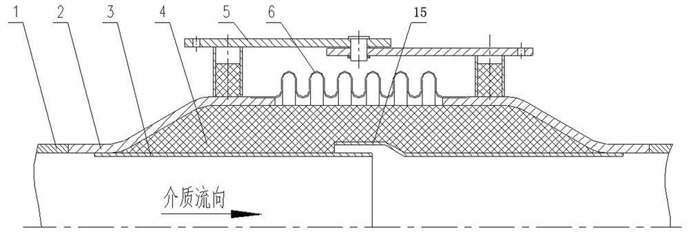
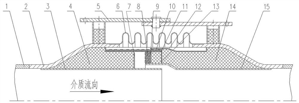
[0022] Such as image 3 As shown, a high-temperature expansion joint with a vibration-proof and heat-insulating structure includes a bellows 6, end pipes 2 connected to both sides of the bellows 6, an inlet guide tube 3 and an outlet guide tube 15, and the outlet guide tube 15 The tail end of the inlet is lapped on the inlet guide tube 3, and there is a gap between the lapped parts, such as figure 1 As shown, the bellows 6, the inlet guide tube 3, the outlet guide tube 15 and the end pipe 2 enclose the heat insulation layer filling space for filling the heat insulation layer, and anti-vibration and heat insulation are provided in the heat insulation layer filling space. Mechanism, anti-vibration heat insulation mechanism includes inn...


PUM


Abstract

A high-temperature expansion joint with an anti-vibration heat insulation structure comprises a corrugated pipe, end pipes connected to the two sides of the corrugated pipe, an inlet guide cylinder and an outlet guide cylinder, a heat insulation layer filling space used for being filled with a heat insulation layer is defined by the corrugated pipe, the inlet guide cylinder, the outlet guide cylinder and the end pipes, and an anti-vibration heat insulation mechanism is arranged in the heat insulation layer filling space. The anti-vibration and heat-insulation mechanism comprises an inner heat-insulation cylinder, an outer heat-insulation cylinder, a heat-insulation annular baffle I, a heat-insulation annular baffle II, a heat-insulation annular baffle III, a heat-insulation annular baffle I, an inlet guide cylinder and an end pipe on the left side of the corrugated pipe, and a space defined by the inner heat-insulation cylinder is filled with a heat-insulation layer I; and a heat insulation layer IV is filled in a space formed by the leftmost heat insulation annular baffle III, the outer heat insulation cylinder, the end pipe on the right side of the corrugated pipe and the outlet guide cylinder. The expansion joint is simple in structure, high in applicability and low in manufacturing cost, effectively reduces the working temperature of the core part corrugated pipe, improves the operation reliability, and guarantees the safety of the device.

Description

technical field [0001] The invention relates to the technical field of expansion joints, in particular to a high-temperature expansion joint with a vibration-proof and heat-insulating structure. Background technique [0002] As a compensator for the pipeline pressure pipeline, the bellows expansion joint can compensate the thermal deformation and mechanical deformation of the pipeline, which can reduce the stress of the pipeline and improve the service life of the pipeline. Especially in the case of high-temperature medium (up to 650°C~750°C), the thermal expansion of the pipe is large, the allowable stress of the material is low, and the risk of medium leakage is high, so the safety performance of the expansion joint is strictly required. The bellows is the core component of the expansion joint. In order to keep the expansion joint in a safe working state, a heat insulation layer is usually installed inside the expansion joint. See figure 1 As shown, reduce the bellows wor...

Claims


Application Information

Patent Timeline
Patent Type & Authority Applications(China)
IPC IPC(8): F16L51/02F16L59/21F16L55/02
CPCF16L51/02F16L59/21F16L55/02
Inventor 杨玉强宫玉才李张治王金富祁鲁海李杰陈杰李德雨杨青谢晓峰
Owner LUOYANG SUNRUI SPECIAL EQUIP
Features
  • R&D
  • Intellectual Property
  • Life Sciences
  • Materials
  • Tech Scout
  • Unparalleled Data Quality
  • Higher Quality Content
  • 60% Fewer Hallucinations
Learn More