Anchor driving tool, anchor driving method, and anchor driving unit
A technology for anchors and tools, which is applied in the field of anchor setting tools, anchor setting and anchor setting units, which can solve the problems of labor and time spent on hitting and inserting anchors, and achieve the effect of restraining load
- Summary
- Abstract
- Description
- Claims
- Application Information
AI Technical Summary
Problems solved by technology
Method used
Image

Examples
Embodiment 1
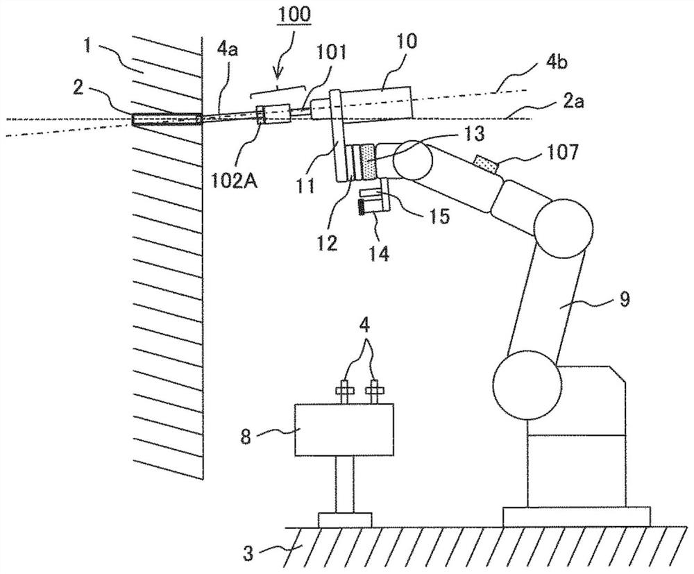
[0043] figure 1It shows the anchor driving device of Example 1 using the anchor driving tool 100 of the present invention, and shows a schematic diagram of attaching the anchor driving device 10 connected with the anchor driving tool 100 to the robot 9 having an arm.
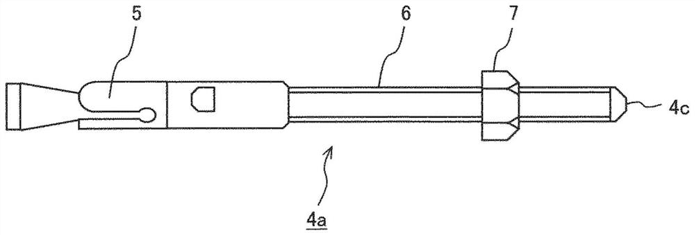
[0044] This figure shows a state in which a robot 9 is installed on an installation surface 3, and one anchor 4a, among a plurality of anchors 4, which is replaceably loaded in an anchor holder 8, is grasped by an anchor driving tool 100, and The front end of the anchor 4a is inserted into the pre-drilled hole 2 perforated in the wall surface 1 .
[0045] More specifically, the driving device 10 to which the anchor driving tool 100 is connected is attached to a driving device holder 11 , and the driving device holder 11 is connected to a tool changer 12 described later.
[0046] In addition, although not shown in the figure, the driving device 10 has a built-in driving shaft for performing the driving operation...
Embodiment 2
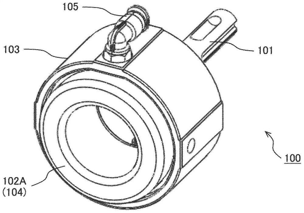
[0086] In the anchor driving tool 100 described in Embodiment 1, the holding portion 102A of the anchor 4a is held by injecting pressurized air into the floating ring-shaped rubber bag 104 to expand the inner diameter of the holding portion 102A. Way.
[0087] As an alternative (embodiment 2) for holding the anchor 4a, in Figure 12 and Figure 13 A gripping method using two opening and closing fingers 200 is shown in .
[0088] The gripping portion 102B of the anchor driving tool 100 of this embodiment consists of two fingers 200, a finger base 201 that drives the fingers 200 to open and close (sliding the root of the fingers 200), And the air pipe joint 105 for supplying compressed air to the finger base 201 in order to open and close the finger 200 is comprised. The grip part 102B of the present embodiment is connected to the beating part 101 in the same manner as in the first embodiment.
[0089] Furthermore, the state in which compressed air is not supplied to the fin...
Embodiment 3
[0097] As an alternative to holding the anchor 4a (Example 3), there is Figure 14 and Figure 15 Drill Chuck style shown. This is the same structure as a general drill chuck, and the anchor 4a is held by the drill chuck instead of the drill.
[0098] That is, the grip portion 102C of the anchor driving tool 100 of the present embodiment is roughly composed of the following parts: a plurality (three in the present embodiment) of claws 301; and a chuck 300 that can be sent out in the axial direction. Three jaws 301 are supported, and the intervals between the three jaws 301 are narrowed or widened; a base 303 supports the chuck 300; and a servo motor 302 is arranged on the base 303 and controls the three The feed amount of each claw 301 in the axial direction and the distance between the three claws 301 are changed by the feed amount of the three claws 301 in the chuck 300 to change the inner diameter surrounded by the three claws 301 (diameter of holding the anchor 4a). 102...
PUM
 Abstract
Description
Claims
Application Information
 - R&D
- Intellectual Property
- Life Sciences
- Materials
- Tech Scout
- Unparalleled Data Quality
- Higher Quality Content
- 60% Fewer Hallucinations
Browse by: Latest US Patents, China's latest patents, Technical Efficacy Thesaurus, Application Domain, Technology Topic, Popular Technical Reports.
© 2025 PatSnap. All rights reserved.Legal|Privacy policy|Modern Slavery Act Transparency Statement|Sitemap|About US| Contact US: help@patsnap.com